Every CNC machinist eventually hits the same wall: the hole has to be bigger than your largest drill, truer than a helical interpolation can hold, or rounder than the mill allows. That is the moment the boring bar earns its place in the tool crib. Yet boring is also the operation most often blamed for chatter, bell-mouthed holes and scrapped parts — almost always because the bar was chosen or set up wrong. This guide covers what a boring bar actually does, why overhang dominates everything, how to pick between steel, carbide and damped bars, and what separates a good fine boring head from a frustrating one.
What a boring bar actually does
A boring bar is a single-point turning tool that rotates inside a hole. One insert, one cutting edge, fed either axially (to straighten and enlarge a hole) or held at depth (to face a counterbore or cut a groove). Because the tool passes over the same surface once per revolution, it removes the error left by the previous operation rather than following it. A hole drilled and then bored will come out rounder, straighter and closer to size than a hole produced by any single drilling or milling strategy of the same diameter.
That is why interpolation with an end mill rarely replaces boring above roughly 50 mm diameter. Milling a circle leaves a polygon effect, depends on the machine’s circularity, and pushes radial load into a thin, flexible tool. A properly set boring bar pushes the cutting force into a stiff, ground bar and lets the insert size the hole directly.
The overhang problem: deflection grows with the cube
If you remember one thing about boring, make it this: cutting-point deflection grows roughly with the cube of the overhang. Double the length from the holder face to the insert, and deflection multiplies by eight — same cutting force, eight times the deviation. This single relationship explains most boring failures: the hole that is oversize at the entry and undersize at depth, the taper that appears only on long bores, the chatter that starts at 90 mm depth but not at 60 mm.
The L/D rule of thumb
Boring bar makers publish maximum overhang as a ratio of overhang to bar diameter (L/D). Exceeding it does not always fail immediately — but each step past the limit costs rigidity faster than most people expect:
- Steel boring bar: practical limit around 4:1. Beyond that, spring passes and taper corrections stop converging.
- Solid carbide bar: roughly 6:1. Young’s modulus for carbide is about 2.5–3× that of steel, so the same section resists bending far better.
- Damped bar (tungsten-filled or internal damper): 8:1 and beyond in many cases, not because the bar is stiffer but because it absorbs the vibration energy that would otherwise amplify.
A worked example
Take a 25 mm steel bar boring a 40 mm hole. At 100 mm overhang (L/D = 4:1) with a light finishing cut — say 50 N of radial force — deflection stays in the low single-digit microns, and a spring pass cleans it up. Push the same cut to 200 mm overhang and the deflection term multiplies by 2³ = 8. Your spring pass no longer converges, the hole measures 20 µm oversize at entry and 8 µm undersize at depth, and the natural response — “reduce the feed” — actually makes it worse, because a lighter cut leaves the insert rubbing instead of cutting. The fix is never a lighter cut at 8× deflection; it is a shorter bar, a larger diameter bar, or a different material.
Steel vs carbide vs damped boring bars
The three common bar materials solve the overhang problem in different ways, at very different costs:
| Property | Steel bar | Solid carbide bar | Damped bar |
|---|---|---|---|
| Relative bending rigidity | Baseline (1×) | ≈ 2.5–3× | ≈ 1× (steel-like body) |
| Vibration damping | Low | Low–moderate | High (internal damper) |
| Practical max L/D | ≈ 4:1 | ≈ 6:1 | ≈ 8:1+ |
| Typical chatter behavior | Chatters past 4:1 | Stiffer, but can still ring | Cuts quietly at long overhang |
| Relative cost | Low | High | Highest |
| Best use | Short bores, general work, through holes | Deep, precise bores in stable setups | Deep bores, interrupted cuts, thin-wall parts |
A practical rule for mixed job shops: stock steel bars for everyday work, and buy carbide or damped bars only for the bores that actually hurt. Most shops that try to standardize on carbide everywhere overspend, because 80% of boring happens under 3:1 overhang where a steel bar is already rigid enough.
Rough boring: removing stock before precision matters
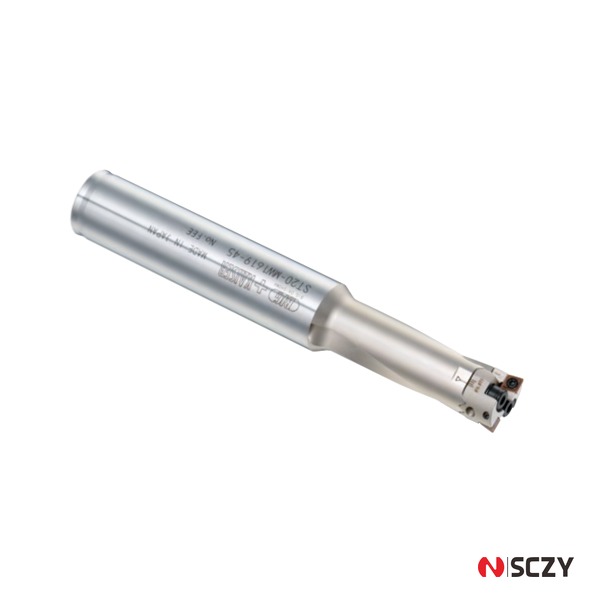
Rough boring exists to turn a drilled hole into a concentric, evenly loaded blank for the finishing pass. Roughing bars — the MW-style bars with one or two indexable inserts — take 2–5 mm of radial stock per side at high feed, and a two-insert “double cutter” setup halves the cycle time while balancing radial load. Three points matter at this stage:
- Bore the minimum you need. Every micron of stock left for finishing is fine; every extra millimeter of roughing stock is wasted cycle time and heat.
- Keep the inserts sharp and matched. On two-insert bars, a worn insert on one side loads the bar unevenly and starts the taper early.
- Watch chip evacuation. In blind bores, roughing chips have nowhere to go. Through-coolant or a peck-retract strategy is not optional past about 3× diameter depth.
Fine boring heads: getting to ±0.005 mm
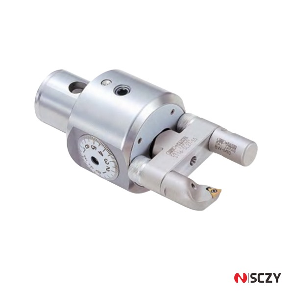
The fine boring head is where boring stops being “big drilling” and becomes sizing. A quality head moves the insert radially in micrometer steps — typically 0.005 mm per graduation on diameter — through a vernier dial or a click-stop mechanism. That adjustment range is what lets you dial a bore in over two or three test cuts instead of shimming an insert by feel.
Reading the dial correctly
The classic mistake is confusing radius and diameter. If the dial reads 0.005 mm per graduation in radius, one click is 0.010 mm on the hole. Heads differ; check the engraving or the manual before the first test cut, and write the convention on the setup sheet. The second mistake is skipping the approach direction: many heads must always approach final size from the same rotational direction to remove backlash. Approaching “downward” onto size leaves the carriage floating on its clearance and gives a hole that varies part to part.
The two-cut discipline
Reliable fine boring follows the same pattern every time: a semi-finish cut leaving 0.10–0.20 mm on diameter, then a finish cut. Measure the semi-finished bore, calculate the exact residual, dial it in, and finish. Trying to go from rough to final in one pass asks the head to remove an unpredictable load, and the deflection error lands directly in the bore.
Balance when the rpm climbs
A fine boring head is an intentionally asymmetrical mass: the sliding carriage sits off-center by design. Below about 3,000 rpm this barely matters. Push toward 6,000–10,000 rpm for small bores and the imbalance shows up as vibration marks and premature spindle bearing wear. Modern heads either offer counterweight rings or are balanced by construction for a stated rpm limit — respect it, and add counterweights symmetrically when the catalog allows.
Speeds, feeds and chatter control
Boring cuts are judged by surface finish as much as size, so the speed/feed combination matters more than in roughing. A few field-tested starting points:
- Surface speed: run coated carbide at the insert maker’s mid-range for the material — around 150–250 m/min in medium-carbon steel, 250–400 m/min in aluminum, 80–140 m/min in stainless. Long overhang? Start at the bottom of the range.
- Feed per rev: 0.05–0.15 mm/rev for finishing with a small nose radius. Too light a feed rubs and work-hardens stainless; too heavy a feed leaves visible feed marks that measurement tools read as out-of-round.
- Depth of cut: finishing radial depth of 0.10–0.30 mm on diameter is typical. Above 0.5 mm you are semi-finishing, and the deflection math changes.
- Chatter first aid: change rpm by ±10–15% first (it moves the vibration away from the resonance), add a reduced-shank or damped bar second, and only then reach for geometry changes like a larger nose radius or positive-rake insert.
Common failure modes and what actually fixes them
- Bell mouth (oversize at entry): the insert deflects as it enters the cut and recovers at depth. Cause is overhang past the bar’s limit, or an excess entry stock step. Shorten the bar or split the roughing pass.
- Taper along the bore: deflection varies with depth as chips and load change, or the bar is rubbing on the bore wall. Check bar clearance, reduce overhang, and verify the insert is seated on its seat pin.
- Chatter marks: resonance between bar, holder and part. Change rpm first, shorten overhang second, switch to a damped bar third. Also check the clamping: a boring bar hanging out of a worn ER collet is a chatter generator no matter how good the bar is.
- Size drift between parts: almost always thermal. A long run heats the bar and the part; the bore grows. Either flood-coolant the bore consistently, or add a mid-run compensation offset.
- Poor surface finish in stainless or titanium: work hardening from a dull edge or rubbing feed. Sharpen the insert schedule and keep the feed above the work-hardening threshold.
Quick selection checklist
- Overhang ≤ 4:1? Steel bar is fine and cheap.
- 4:1 to 6:1? Solid carbide bar.
- Beyond 6:1, or interrupted cuts? Damped bar.
- Tolerance tighter than ±0.01 mm? Fine boring head with micrometer dial — and use the two-cut discipline.
- Rpm above 3,000? Check the head’s balance rating.
- Blind bore deeper than 3× diameter? Plan chip evacuation before the first cut.
Boring rewards the shops that respect one variable above all: overhang. Pick the bar material to match your L/D, put the adjustment burden on a quality fine boring head, and treat chatter as a setup symptom rather than a tool defect. Do that, and a boring bar delivers hole quality that no interpolated end mill path can match.
Need help matching a boring bar, fine boring head or the right holder to your machines? Contact the SCZY team — we supply tool holders, workholding and precision tooling for machining centers, and we are glad to review your application before you buy.