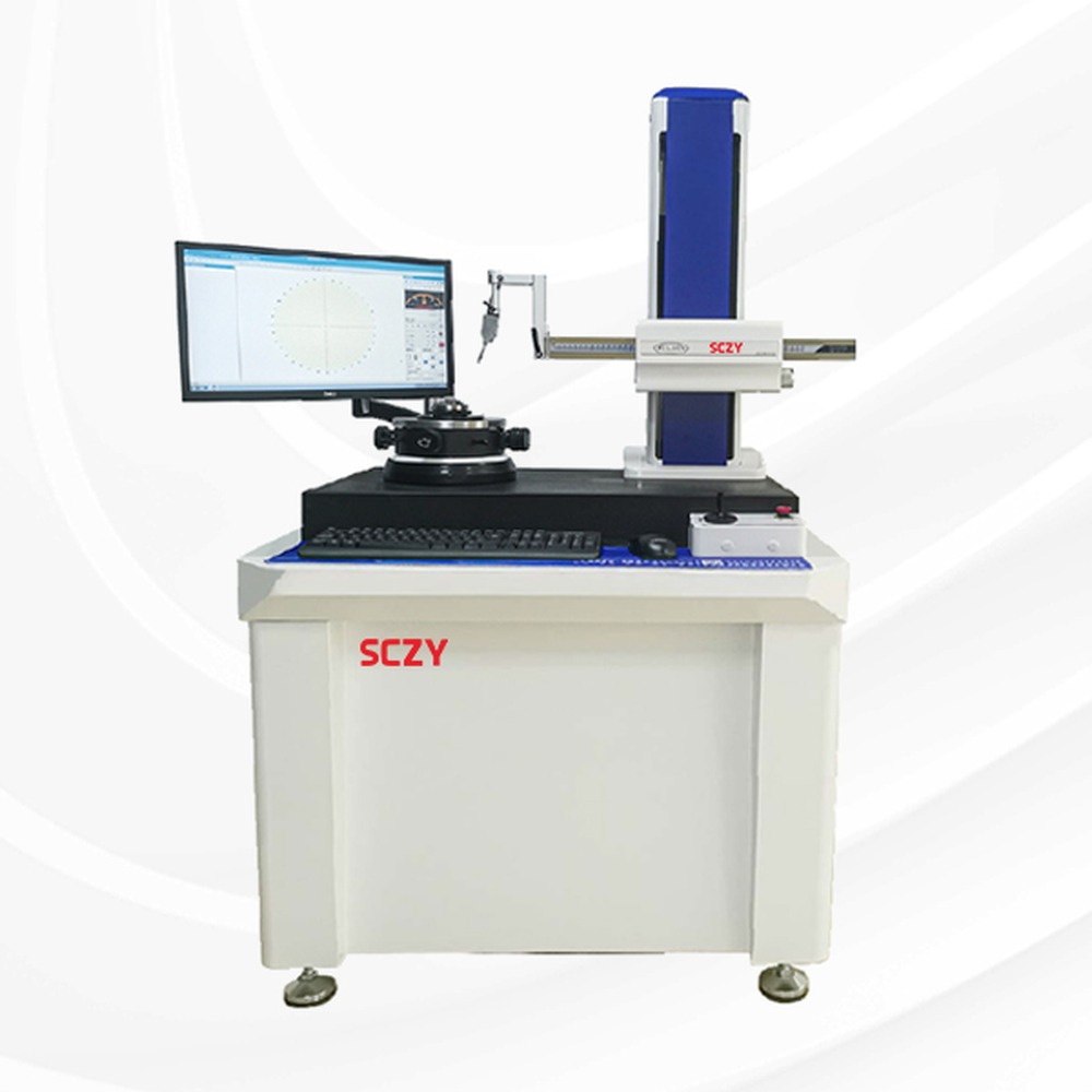
A bearing bore that passes a micrometer check can still fail on the assembly line, and a hydraulic spool can measure within tolerance on diameter yet leak past its seal because the bore is slightly lobed. Those defects are invisible to two-point measurements — exactly what a roundness tester is built to find. If your parts carry roundness or cylindricity callouts below a few microns, a dedicated roundness tester is usually the right instrument. This guide explains how these machines work, how the two main architectures differ, what the evaluation and filter settings do to your numbers, and when you actually need one.
Why Roundness Needs Its Own Machine
Roundness (circularity in ISO GPS language) is the radial deviation of a single cross-section from a perfect circle. Calipers and micrometers compare only two points at a time, so they cannot verify it: a three-lobed part measures identical across every pair of jaws yet is badly out-of-round — the classic result of grinding a ring in a three-jaw chuck. Runout on a vee-block is not the answer either, because it mixes surface form with datum and setup errors. A roundness tester removes setup geometry by measuring radial displacement against an independent reference spindle, so the reported number is the true geometric deviation of the surface itself.
How a Roundness Tester Works
Every roundness tester shares the same core: a reference rotation of known accuracy, a radial displacement probe, and software that converts the signal into a profile and a deviation value. What differs is where the rotation lives — in the table under the workpiece, or in the spindle carrying the probe.
The Rotating Table Design
In a rotating table machine, the part sits on a precision spindle — often an air bearing — and rotates under a stationary probe. This is the most common architecture for shop-floor and lab instruments because it handles the widest range of workpieces: heavy or off-balance components are fine as long as they fit within the load rating. The trade-off is setup quality. A badly centered part dominates the trace with a large first-harmonic sine wave that software must remove mathematically, amplifying noise — so centering and leveling are done properly on the machine’s screens, not by eye.
The Rotating Spindle Design
Here the probe rotates around the stationary part on a reference spindle. Since the part never moves, its mass and balance are irrelevant — the design excels for large, heavy components such as crankshafts and housing bores that would be impractical or unsafe to rotate. The limitation is geometry: the probe must reach the feature, so deep internal features and long bores may need extended styli, and multi-section cylindricity requires repositioning the vertical axis between traces.
The Four Evaluation Methods Behind Every Roundness Number
A raw trace is a polar plot of radial displacement. To turn it into one number, the software fits a reference circle — and there are four accepted ways to do it, each with a different value on borderline parts.
Least Squares Circle (LSC), the default in most software, minimizes squared radial deviations. It is fast, stable and statistically robust — the standard for process control — but slightly under-reads deep, narrow lobing. Minimum Zone Circle (MZC) finds the two concentric circles that just contain the profile with minimum radial separation. It matches the ASME Y14.5 definition of circularity, always reports a value equal to or smaller than LSC, and is what you should use when the drawing specifies a geometric tolerance without naming a fitting criterion.
Maximum Inscribed Circle (MIC) is the largest circle contained within the profile — the largest perfect plug that would fit the bore — so it is right for evaluating bores against functional assembly. Minimum Circumscribed Circle (MCC) is the smallest circle enclosing the profile, the smallest ring that would slide over a shaft, which makes it the natural choice for pins and shafts.
The practical point: the same ground bore can read 1.2 µm with LSC and 0.9 µm with MZC. If the customer measures with MZC and you inspect with LSC, you will reject good parts. Always confirm which method the drawing or customer procedure specifies, and mirror it.
Filtering: Why the Same Part Shows Different Roundness Values
Before fitting, the software filters the profile. Standard bands are named by undulations per revolution (UPR): a 15 UPR low-pass gives the classic form roundness value, 50 UPR suits fine finishes and precision bearings, and 500 UPR keeps harmonic content tied to waviness and vibration. Change the filter and the number changes — a 2 µm reading at 15 UPR can easily become 3 µm at 500 UPR because chatter is no longer filtered out.
This is deliberate metrology, not a loophole: the filter must match the feature’s function. A bearing race cares about broad lobing that affects oil film thickness, so a low UPR cutoff is correct; a seal interacts with finer waviness, so a wider band is justified. When comparing results with a supplier report, confirm filter settings as well as evaluation method — mismatched filters cause most “your machine reads differently” disputes.
From Roundness to Cylindricity Measurement
Roundness evaluates one cross-section. Cylindricity evaluates the whole cylindrical surface: form across multiple traces plus the alignment of their axes, capturing taper, bow and axis curvature. That makes cylindricity measurement more than several roundness readings — the software must acquire traces at different heights (or a continuous helix) and combine them into one cylindrical reference surface. Vertical straightness and the parallelism of rotation axis to vertical travel now enter the error budget, which is why cylindricity-capable machines carry tighter column specifications. If your drawings are moving to cylindricity callouts — common on fuel system, hydraulic and bearing work — confirm multi-trace cylindricity ships with the base software, not as a paid add-on.
Rotating Table vs Rotating Spindle: Choosing the Architecture
The table below compares the two roundness tester architectures with the alternatives shops sometimes use.
| Attribute | Rotating table roundness tester | Rotating spindle roundness tester | CMM circle scan | Vee-block + dial indicator |
|---|---|---|---|---|
| Typical radial accuracy | 0.02–0.1 µm spindle error | 0.02–0.05 µm spindle error | ~0.5–2 µm, machine dependent | Not a geometric measurement |
| Workpiece handling | Part rotates; limited by table load and balance | Part stationary; best for heavy or large parts | Part fixed; probe moves | Manual rotation |
| Cylindricity capability | Yes, with vertical axis travel | Yes, with vertical axis travel | Approximate; slow, high uncertainty | No |
| Evaluation and filtering | LSC/MZC/MIC/MCC, UPR filters, harmonics | Same as rotating table | Basic form fitting only | None |
| Throughput | Fast once centered; seconds per trace | Slower vertical repositioning between traces | Slow | Quick but low information |
| Best for | Bearings, rings, pistons, seals, small-medium batches | Crankshafts, housing bores, large shafts | Occasional checks when a CMM exists | Shop-floor screening only |
For most first-time buyers, the rotating table design is the safer choice: faster for the mixed small and medium parts typical of precision machining, with simpler operator setup. The rotating spindle earns its premium when parts are too heavy to rotate or features are only reachable from awkward angles.
Roundness Tester or CMM: Matching the Instrument to the Tolerance
For roundness tolerances above roughly 5 µm on accessible features, a CMM with a scanning head gives useful numbers. Below that, the CMM’s probe uncertainty and machine geometry consume a large fraction of the tolerance band and results turn noisy. Apply the 10% rule: measurement uncertainty should stay under one tenth of the tolerance. A drawing calling 2 µm circularity on a bearing seat needs a dedicated roundness tester with sub-micron spindle error — no general-purpose CMM in this class will give a trustworthy pass/fail.
The reverse is equally true: a roundness tester does not replace a CMM. Depending on software it adds coaxiality, concentricity, perpendicularity and face flatness, but it will not check location across prismatic features. The two instruments complement each other — CMM for location and size, roundness tester for form on critical rotating and sealing surfaces.
Getting the Setup Right: Where Most Roundness Errors Come From
Three setup errors corrupt more rotating-table measurements than the instrument ever will. Eccentricity: the part axis must sit close to the spindle axis, or the trace is dominated by a huge sine wave whose numerical removal amplifies noise. Leveling: a tilted part axis turns the cross-section into an ellipse — on a Ø50 mm part, a 0.5° tilt adds roughly 10 µm of apparent roundness error. Surface condition: chips, burrs or a dirty table face shift the axis between centering and measurement; clean both surfaces every time and wipe coolant film off ground parts.
And note what a roundness tester does not check: surface finish. A part can be perfectly round and still rough, so where both form and finish are specified, pair it with a surface roughness tester or stylus profilometer — the instruments share sample preparation and often the same bench.
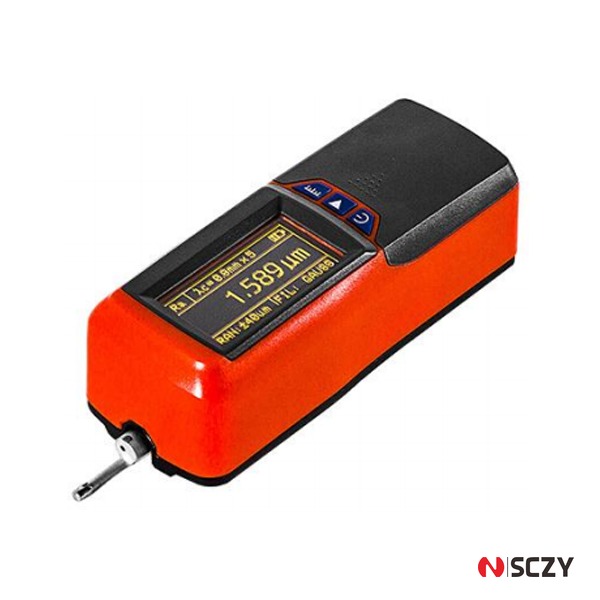
What to Check Before You Buy
Spindle radial and axial error is the fundamental accuracy limit — ask for the MPE value at the measurement face, not a best-case figure; for 1 µm tolerances you want 0.05 µm or better. Evaluation software scope: confirm all four fitting methods, UPR filter control, harmonic analysis and cylindricity are included, since vendors often gate these behind options worth 30–50% of the price. Table load and part envelope: check mass, diameter and height against your heaviest realistic part. Vertical straightness and axis parallelism matter only if you will measure cylindricity — get them in writing for full Z travel. Styli range: bores from Ø3 mm to Ø300 mm need different styli lengths and tip radii. Traceable calibration: required in most automotive and aerospace supplier agreements. Finally, ask for a live demo with your own part, timing a full centering-leveling-measure-report cycle — the best instrument is the one your inspectors will actually run.
Putting It Together
A roundness tester is a narrow, deep instrument: one family of measurements at an accuracy no general-purpose machine can match, rewarding disciplined setup and correctly chosen evaluation and filter settings. If your parts include bearing seats, hydraulic bores, spools or sealing surfaces with sub-5 µm circularity callouts, it pays for itself in avoided rejected-part disputes. Choose rotating table for mixed small and medium batches, rotating spindle for heavy components — and confirm the software includes all four fitting methods and full filter control before signing.
If you are evaluating roundness testing for your quality lab or want a second opinion on inspection data from a customer audit, our team works with these instruments daily alongside our CNC tooling and workholding business. Contact SCZY and we will help you match the measurement method to the drawing — before you buy, not after.