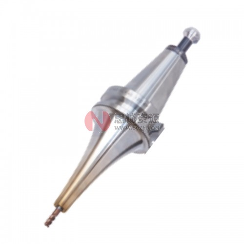
Every rotating tool holder leaves the factory with a balance condition, whether or not anyone talks about it. At low spindle speeds it barely matters. At 15,000 rpm it decides whether your spindle bearings last five years or five months. The confusing part for most buyers is that the grades — G16, G6.3, G2.5, G1.0 — look like abstract quality labels when they are actually a precise engineering contract. This guide explains what tool holder balancing grades really mean, how to convert a G grade into grams·millimeters you can actually verify, and when paying for a G2.5 balance grade is worth it.
Why Unbalance Wrecks Spindles Long Before You Notice It
An unbalanced holder rotating at speed generates a centrifugal force that grows with the square of rotational speed. Double the rpm and the shaking force quadruples. That force acts directly on the spindle bearings as a radial load they were never designed to carry, and it shows up in your parts as chatter marks, waviness on finish passes, and tool life that randomly varies between pockets.
The practical sequence usually looks like this: first the surface finish degrades on long-reach or finishing operations, then tool life becomes inconsistent, then the spindle starts running warm, and finally bearing replacement becomes a five-figure repair. Because the symptoms appear gradually, shops often blame the cutting tool or the CAM strategy when the root cause is a cheap, unbalanced holder spinning at 18,000 rpm.
What the G Grade Actually Means (ISO 21940 / Formerly ISO 1940-1)
The G grade defines the eccentricity of the rotor’s center of mass: G2.5 means the center of mass is offset from the rotation axis by at most 2.5 micrometers; G6.3 allows 6.3 micrometers. That is why the permissible residual unbalance depends on both the mass of the holder and the speed it will run at:
Uper (g·mm) = 9549 × G × M (kg) / n (rpm)
Take a typical BT40 ER collet chuck weighing 1.8 kg, running at 20,000 rpm, specified at G2.5:
U = 9549 × 2.5 × 1.8 / 20,000 ≈ 2.15 g·mm
That is roughly the weight of a paperclip acting at the outer radius of the holder. It is a tight target, and it is exactly why serious manufacturers balance each holder on a machine and verify it, rather than just milling it “symmetric enough.”
G2.5 vs G6.3 vs G16: The Numbers Side by Side
The table below converts the grades for that same 1.8 kg holder at 20,000 rpm, so you can see how quickly the tolerance tightens:
| Balance grade | Residual unbalance limit (1.8 kg @ 20,000 rpm) | Comfortable speed range (BT/CAT taper) | Typical use |
|---|---|---|---|
| G16 | ≈ 13.8 g·mm | Below 8,000 rpm | General milling and drilling, rough work |
| G6.3 | ≈ 5.4 g·mm | 8,000 – 12,000 rpm | Standard machining centers, everyday production |
| G2.5 | ≈ 2.2 g·mm | 12,000 – 25,000 rpm | High-speed machining, finishing, mold work |
| G1.0 | ≈ 0.9 g·mm | Above 25,000 rpm | HSK-E, small taper spindles, micro tooling |
Two conclusions fall straight out of the table. First, if your spindles never exceed 8,000 rpm, a G6.3 holder is not a compromise — it is the correct specification, and paying for G2.5 buys you nothing measurable. Second, the grade only means something at a stated speed. A holder “balanced to G2.5” without a speed limit on the drawing is marketing, not engineering. Reputable suppliers engrave both values on the body.
Where the Unbalance Actually Comes From
When a balanced holder starts shaking at speed, the cause is almost never the taper body itself. CNC tool holders are turned and ground on precision machines, and the body is usually the smallest contributor. The unbalance creeps in from the parts people swap, wear, and abuse:
1. The Pull Stud / Retention Knob
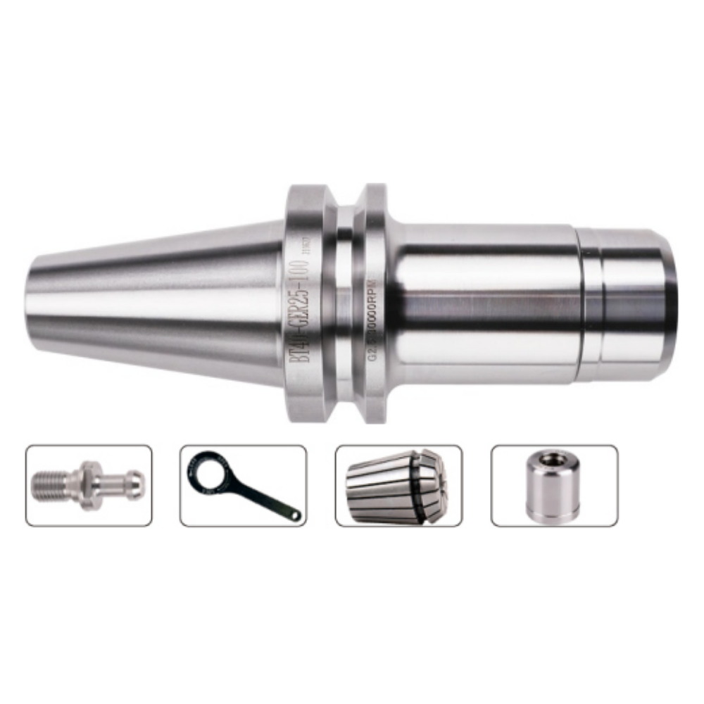
A mismatched or counterfeit pull stud shifts the assembly’s center of mass along the axis and adds radial offset. It sits close to the spindle front bearings, so its contribution to bearing load is significant. Pull studs should be bought to the machine tool builder’s drawing, not to whatever is cheapest in the drawer.
2. The Collet, Clamping Nut and Set Screws
On ER-type holders the clamping nut is often the single largest unbalance source — it rotates at full speed and carries the collet with it. Cross-slotted nuts and worn threads make it worse. On Weldon and side-lock end mill holders, the set screw itself is an intentional asymmetry: a single screw sticking into the flange is a designed imbalance that must be compensated elsewhere.
3. The Cutting Tool and Coolant Holes
Deep axial coolant holes that are not perfectly symmetric, and milling cutters with asymmetric pocket geometry, add unbalance that no amount of holder quality can remove. This is why high-speed shops balance the assembled tool, not just the holder body.
How to Check What You Actually Bought
Read the Engraving First
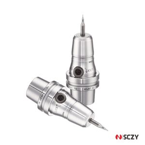
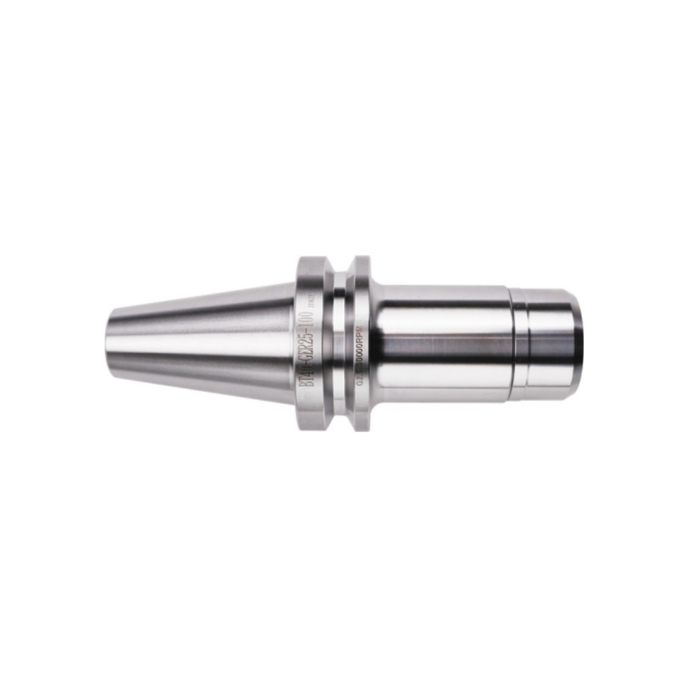
Quality holders state two things on the body: the balance grade and the maximum speed it is valid at, for example “G2.5 / 20,000 RPM.” If a holder has no marking at all, assume G6.3 at best and treat it as an under-8,000-rpm component. A marking with a grade but no speed limit deserves the same skepticism.
Runout Is Not Unbalance
These two get mixed up constantly, and the distinction matters when you are rejecting parts. Runout (TIR) is a geometric error measured at standstill with a dial indicator — it tells you how concentric the collet pocket is, typically 3–5 µm on a good holder. Unbalance is a mass distribution error that only exists at speed. A holder can pass a runout check perfectly and still be badly unbalanced because of its nut or pull stud. Conversely, balancing the holder does nothing for a 20 µm runout problem. Inspect both, with different tools.
Practical Rules: When Balancing Starts to Pay Off
Full dynamic balancing on a machine costs money and lead time. Here is the decision logic we recommend to buyers, matched to spindle speed:
- Below 8,000 rpm: G6.3 is sufficient. Spend the budget on runout and taper quality instead.
- 8,000 – 12,000 rpm: G6.3 works for robust roughing; choose G2.5 for finishing and long-reach tools where vibration directly hits surface finish.
- 12,000 – 20,000 rpm: G2.5 on the holder is the baseline. Check the nut and pull stud quality with equal seriousness.
- Above 20,000 rpm: Balance the complete tool assembly (holder + collet + cutter) on a balancing machine, and specify prebalanced or symmetric clamping nuts. This is standard practice in HSK-A63/E25 and BBT40 environments.
One more rule worth remembering: balance grade applies to the whole rotating assembly. A G2.5 holder with a bargain-bin nut and a mismatched pull stud is, in practice, a G16 assembly.
Balancing the Assembly vs Buying Prebalanced Components
Assembled-Tool Balancing
For dedicated high-speed jobs — a mold cavity finish, an aerospace aluminum part run for weeks — mounting the exact tool assembly on a balancing machine and correcting it in one or two planes gives the best possible result. The downside is that the balance is valid only for that specific assembly; change the cutter length and you are back to square one.
Prebalanced Components
For general-purpose shops, the more economical path is buying holders manufactured and verified to G2.5, paired with balanced clamping nuts and certified pull studs. Each component meets the grade on its own, and most reasonable assemblies stay close to it. This is how the majority of 12,000–18,000 rpm BT40 and CAT40 shops operate in practice.
What We Verify Before a Holder Ships
As a sourcing and quality-control partner for CNC tooling, we treat balance as an inspectable specification, not a promise. Before any high-speed holder leaves our partner factories, three checks are recorded: taper and flange geometry against the DIN standard, cutting-edge runout at 4×D, and residual unbalance on a dynamic balancing machine with the grade and max rpm laser-engraved on the body. Holders that cannot hold their marking get reworked or rejected — the engraving is a contract with the end user, and it should be treated that way by any supplier you buy from.
Quick Decision Checklist
- Know your spindle’s realistic top rpm per taper size — that number, not the brochure maximum, sets the required grade.
- Under 8,000 rpm: G6.3, spend on runout quality.
- 8,000–20,000 rpm: G2.5 holders + balanced nuts + correct pull studs.
- Above 20,000 rpm or HSK: balance the assembled tool, insist on two-plane capability.
- Verify the marking: grade AND speed limit, engraved, not printed on a sticker.
- Inspect runout and unbalance separately — one dial indicator cannot do both jobs.
If you are stepping up to higher spindle speeds and are not sure whether your current holders should follow, our engineers can review your machine list and recommend the right balance grades, holders and pull studs for each spindle — before a bearing fails and makes the decision for you.
Ready to upgrade your tool holding? Send us your spindle specs and top speeds, and we will quote holders balanced to the grade your speed actually requires — with the inspection report included.