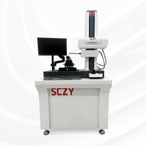
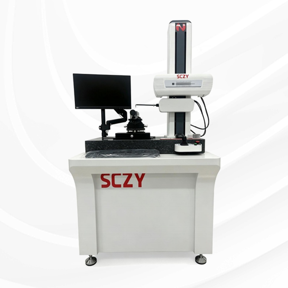
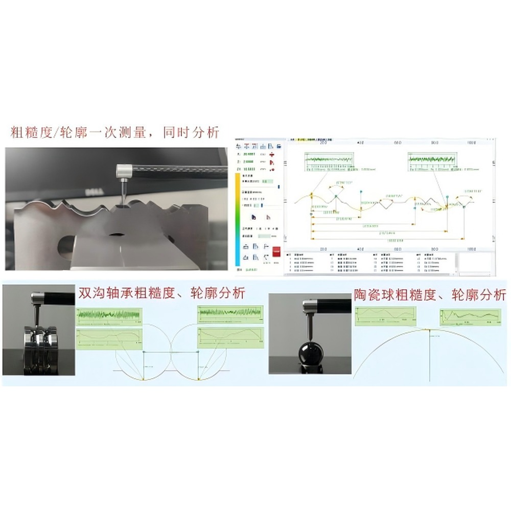
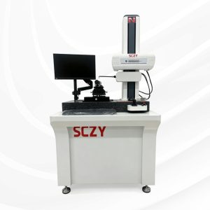
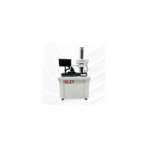
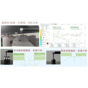
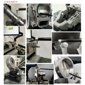
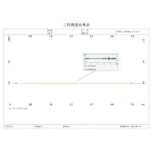
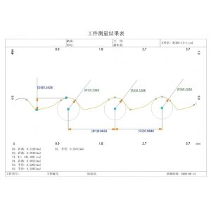
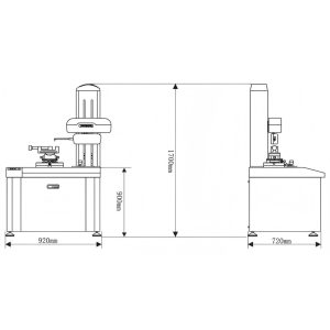
The instrument uses a Cartesian coordinate method with a contact stylus. The X axis runs on a high-precision linear guide as its reference and the Z1 axis uses a digital sensor, so the coordinate points of the workpiece surface profile are mapped directly. The software then processes the raw sensor data mathematically and labels the required measurement items.
Technical highlights
- Roughness, waviness and profile are analysed in a single pass, with no sensor or stylus changeover
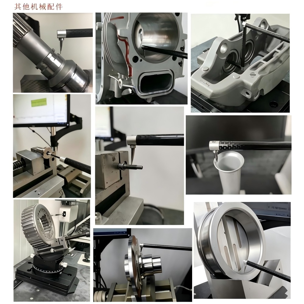
- Roughness and waviness can be measured in fine features, deep holes and deep grooves
- X axis on a linear guide: no wear, high accuracy, long service life
- Z1 axis uses an imported digital sensor: high accuracy and good linearity
- Simple stylus changeover: fit once, no recalibration
- Software switches between Chinese and English with one click; Windows 7, 10 and 11 supported
- Annotation works like CAD: arcs and lines are recognised automatically
- DXF import and export, plus custom CAD format export
- Continuous and datum annotation, insertion points anywhere
- Graphics and coordinates rotate freely
- Raw data saved automatically for repeat annotation
- Mirror function, annotated files can be saved
- Live monitoring of X and Z1 positions
- Automatic stylus contact, lift and retract
- Unlimited undo and redo
- Angle, arc, horizontal, vertical and linear annotation work even without proportional scaling
Measurement functions
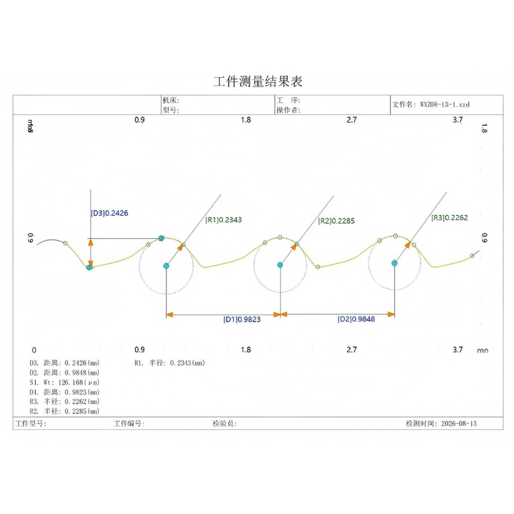
- Size: horizontal distance, vertical distance, linear distance, radius, diameter
- Angle: horizontal angle, vertical angle, included angle
- Position tolerance: parallelism, perpendicularity
- Form tolerance: straightness, crown, arc profile
- Construction: auxiliary points, auxiliary lines, auxiliary circles
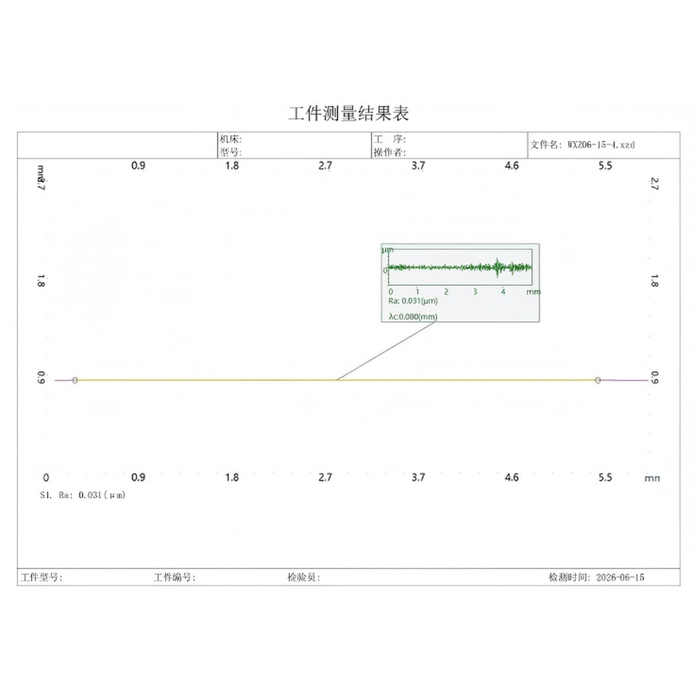
- Roughness analysis: Ra, Rq, Rz, Rp, Rt, Rsk, Rsm, Rc, Rz(DIN), R3z, Rz(JIS), Rpmax, Rpm, Rku, Rdq/R delta q, R delta C, Mr1, Mr2, Rpk, Rvk, Rk, Rdc, A1, A2, Rx, AR, Rpc, Rmax, Rz-ISO, 4 um, Ry
- Waviness analysis: Wt, Wa, Wp, Wv, Wq, Wc, Wku, Wsk, W, Wx, Wz, Wsm, Wdc, Wte, Wmr, Aw, C(Wmr), Wmr(C), Wdq/W delta q
- Primary profile analysis: Pt, Pa, Pp, Pv, Pq, Pc, Pku, Psk, Pdq/p-q, Psm, Pdc, Pmr(c), Pz, Pmr, C(pmr)
Installation data
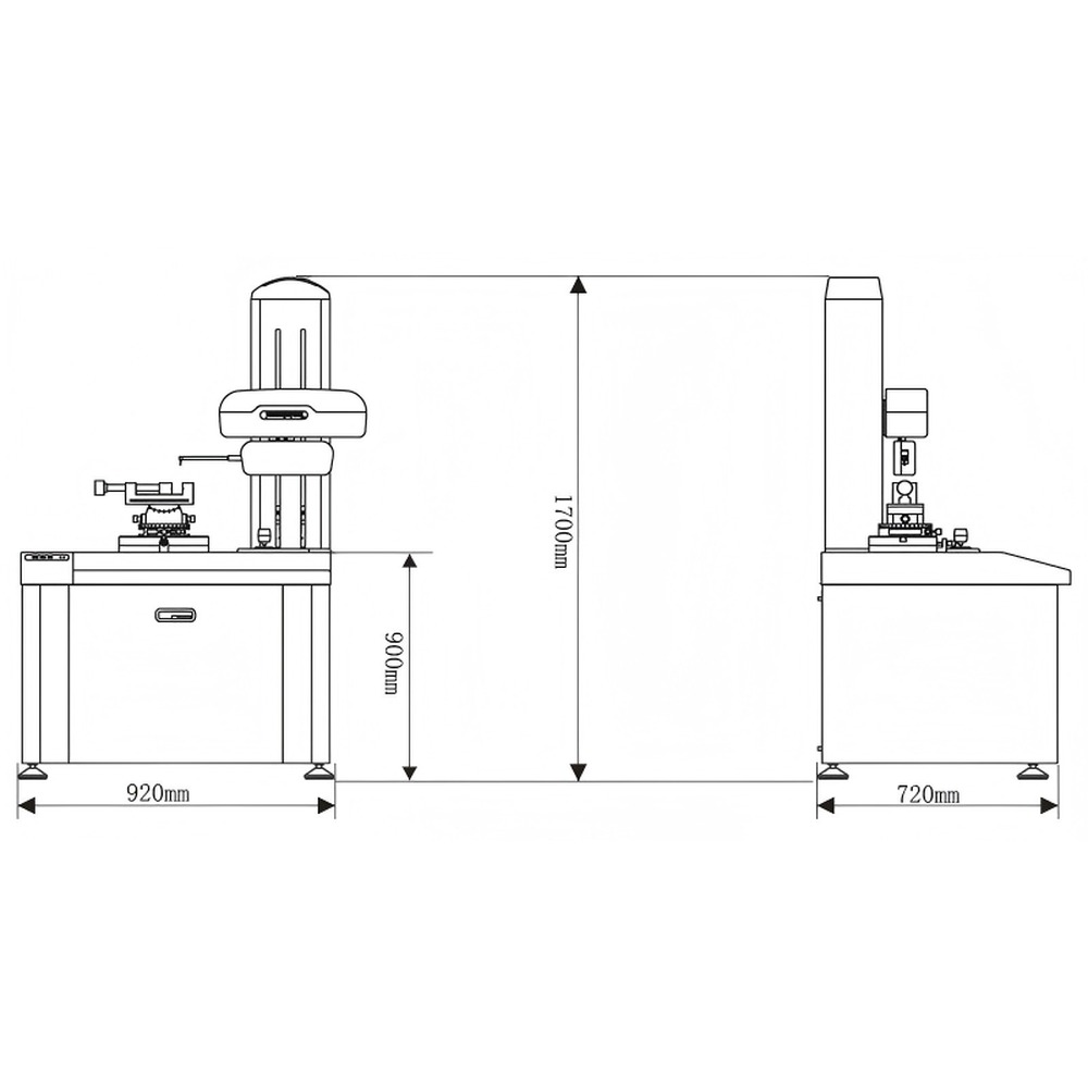
Total weight and volume are given on the specification table below.
Operating requirements
- Power: AC 220 V plus or minus 10 percent, 50 Hz
- Environment: temperature 10 to 30 degrees C, relative humidity below 85 percent, no obvious vibration source near the installation, dedicated earth line
Technical parameters
- Z1 sensor shared by roughness and profile
- X axis travel L equals the guide travel distance
- Z1 axis measuring height H
- Straightness within plus or minus 1
- Arc R equals the standard arc value
- Z1 sensor for both profile and roughness
- Levelling system: overall size 250 x 180 x 40 mm, adjustment range 15 mm
- Rotary and angle setting system: 360 degree rotation, plus or minus 25 degree tilt
- Vice clamping system: jaw width 50 mm, jaw depth 25 mm
| Item | Parameter | |
|---|---|---|
| Measuring Range | X-axis drive | 100mm |
| Z1 sensor, shared by roughness and profile | 40mm | |
| Column Height | 500mm | |
| Indication accuracy | X axis (L = guide travel) | ±(0.8+0.02L)μm |
| Z1 axis (H = measuring height) | ±(0.8+0.02H)μm | |
| Residual Profile | ≤0.005μm | |
| Indication Error | ≤±(5nm+0.1A) | |
| Repeatability | 1δ≤2nm | |
| Angle | ≤±1 ‘ | |
| Arc (R = nominal arc value) | ≤±(1.0+R/12)μm | |
| X-axis drive | Straightness | 0.8μm/100mm |
| Resolution | 0.05μm | |
| Z1 sensor, shared by profile and roughness | Type | Grating Sensor |
| Resolution | 0.01μm | |
| Stylus shared by roughness and profile | 12 deg single-facet stylus, R 0.025 mm | |
| Roughness stylus | 60 deg diamond conical stylus, R 2 um | |
| Climbing angle | Up 77 deg, down 88 deg | |
| Evaluation Length | λc×3、4、5、6、7 | |
| Cut-off Wavelength | 0.025、0.08、0.25、0.8、2.5、8mm | |
| Measuring Mode | Sensor movement | |
| Motion Control | Guide speed | 0.02 mm to 6 mm/s |
| Column movement speed | 0.1 mm to 10 mm/s | |
| Measuring Speed | 0.02 mm to 5.0 mm/s |
| Component | Item | Qty |
|---|---|---|
| Mechanical Section | Main Instrument Frame | 1 |
| Granite Worktable | 1 | |
| Linear Guide Drive | 1 | |
| Motorised Column | 1 | |
| Grating Sensor | 1 | |
| Adjustment Table | Levelling System Dimensions 250 x 180 x 40 mm, adjustment range 15 mm | 1 |
| Rotary and tilt system: 360 deg rotation, plus or minus 25 deg tilt | 1 | |
| Vice clamping: jaw width 50 mm, jaw depth 25 mm | 1 | |
| Calibration Standard | 1 | |
| Probe tip and stem | Dia. 3 x 21 mm, R25 um, 12 deg single-facet stylus | 2 |
| Dia. 1 x 10 mm, R2 um, 60 deg roughness stylus | 1 | |
| 8 x 150 mm probe | 1 | |
| Electrical Section | Electrical Control System | 1 |
| Brand-name PC | 1 | |
| HP inkjet printer | 1 | |
| Measuring Software | 1 | |
| Documents | User Manual | 1 |
| Warranty Card | 1 | |
| Packing List | 1 | |
| Certificate | 1 | |
| Acceptance Record | 1 | |
| Tool Box | 1 |
| Product | Packing | Total Weight (kg) | Volume (CBM m³) | ||||||
|---|---|---|---|---|---|---|---|---|---|
| Lx | Ly | Lz | Wt(kg) | Lx | Ly | Lz | Wt(kg) | ||
| 920 | 720 | 1700 | 350 | 960 | 800 | 1750 | 50 | 400 | 0.88 |