Most shops pick a BT30 tool holder or a BT40 holder based on whatever the machine came with, then spend years working around the consequences. That is backwards. The taper is not a preference — it is the physical limit on how much cutting force you can push through the spindle before the connection starts to deflect, chatter, or lose the tool. Getting the choice right at the machine-selection stage is cheap. Getting it wrong shows up later as unexplained chatter on a face mill, poor hole position on a deep bore, or a tool life curve that never reaches the catalogue numbers.
This guide compares BT30 and BT40 on the dimensions that actually change cutting behaviour, then maps each taper to the work it genuinely suits. If you already own the machine, the same logic tells you how hard you can push the holders you have — and where you should stop.
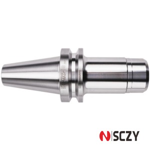
The Short Answer
BT30 suits drill-tap centres, compact vertical machining centres, and high-speed light-cutting applications in aluminium. BT40 suits general-purpose VMCs cutting steel, stainless, and tool steel where you need radial stiffness and a real drawbar force behind the holder. If a job needs a Ø50 mm face mill at 3 mm depth of cut in P20, no BT30 spindle will do it well, and no amount of premium holder selection will fix that. If a job is Ø8 mm end mills at 15,000 rpm in 6061, BT40 is dead weight you are accelerating and decelerating all day.
What Actually Changes Between the Two Tapers
Flange size and taper contact area
Both tapers are 7:24 self-releasing, so the geometry is the same family. The difference is scale. BT30 has a 46 mm flange and a much smaller taper cone; BT40 has a 63 mm flange. Contact area on the taper grows roughly with the square of the diameter, so a BT40 interface carries a substantially larger load-bearing band. That band is what resists bending moment at the tool tip.
Drawbar force is the real limiter
A BT30 spindle typically pulls with something in the 3–5 kN range. A BT40 spindle normally sits around 10–15 kN, with production machines reaching higher. Drawbar force is what keeps the taper seated when a side load tries to peel the holder out of the spindle. It is also why the same holder geometry behaves differently on two machines: a tired BT40 drawbar at 7 kN is closer to BT30 territory than the spec sheet suggests. Check drawbar force with a gauge before blaming the holder for chatter.
Stiffness and depth of cut
As a practical rule, a BT40 connection is roughly twice as resistant to bending at the gauge line as a BT30 connection of similar projection. That doubles your usable depth of cut and lets you hang a longer, larger-diameter tool out front without the assembly turning into a tuning fork. It is an approximation, not a guarantee — but it explains why BT30 shops end up doing multiple light passes where a BT40 shop does one heavier pass.
Mass, tool change time, and spindle acceleration
A BT30 collet chuck typically weighs well under 1 kg; a comparable BT40 holder is often twice that. On a machine doing 4-second tool changes thousands of times a shift, holder mass matters — to the ATC cam, to spindle acceleration, and to how confidently you can run 15,000 rpm all day. This is the strongest argument for BT30 that is not about footprint.
BT30 vs BT40 vs BT50: Specification Comparison
| Parameter | BT30 | BT40 | BT50 |
|---|---|---|---|
| Taper | 7:24 | 7:24 | 7:24 |
| Flange diameter | ≈ 46 mm | ≈ 63 mm | ≈ 100 mm |
| Pull stud thread | M12 | M16 | M24 |
| Typical pull stud torque | 25–35 N·m | 60–80 N·m | 120–160 N·m |
| Typical drawbar force | 3–5 kN | 10–15 kN | 18–25 kN |
| Typical holder weight | 0.5–1.0 kg | 1.2–2.2 kg | 4–7 kg |
| Common collet sizes | ER16 / ER20 / ER25 | ER20 / ER32 / ER40 | ER40 / ER50 |
| Practical end mill ceiling (steel) | Ø12–16 mm | Ø25–32 mm | Ø50 mm and above |
| Typical spindle speed band | 8,000–16,000 rpm | 6,000–12,000 rpm | 3,000–8,000 rpm |
| Best fit | Drill-tap centres, small VMCs, aluminium | General VMC work, steel, moulds | Heavy roughing, large faces |
Treat the numbers as planning values, not machine specifications. Spindle builders vary widely, and a high-end BT30 spindle with 20,000 rpm and a rigid frame will outperform a cheap BT40 on light work. Always confirm against the machine builder’s data before you commit a process.
Where BT30 Wins
Drill-tap centres and small parts
On a drill-tap centre running M3 to M10 taps and Ø10 mm drills in aluminium or brass, BT30 is the correct answer. Short tool changes, small holders, and a compact ATC keep cycle times down. Forcing BT40 onto that class of machine buys stiffness nobody needs and costs seconds on every tool change.
High-speed aluminium and graphite
Above roughly 12,000 rpm, holder mass and balance become more important than raw taper stiffness, because the cuts are light and the failure mode is vibration, not deflection. A balanced BT30 ER collet chuck running a Ø6 mm three-flute cutter at 18,000 rpm is a smoother system than a heavier BT40 assembly fighting the same duty.
Small-footprint cells and automation
Robot-tended cells live or die on magazine density. BT30 holders pack more tools into the same chain or matrix, which directly increases how many jobs you can run lights-out without a manual changeover.
Where BT40 Wins
Steel, stainless, and interrupted cuts
Any operation with a real side load — shoulder milling in 4140, slotting stainless, roughing a welded fabrication — wants the larger taper. The BT40 flange and higher drawbar force keep the assembly seated when the cutter is hammering the workpiece. On BT30 the same cut usually shows up first as a fading surface finish, then as taper fretting.
Long projection and deep pockets
When you must hang a tool 120 mm or more past the gauge line, every millimetre of taper diameter earns its keep. BT40 extended-nose holders stay usable at projections where BT30 assemblies start singing.
Mould and die work
Mould finishing is a compromise between long, small-diameter cutters and surface quality. Extra stiffness lets you run those cutters at a higher feed per tooth without the surface breaking into chatter marks, which is why mould shops standardise on BT40 or larger.
Choosing the Right Holder Inside Each Taper
ER collet chucks
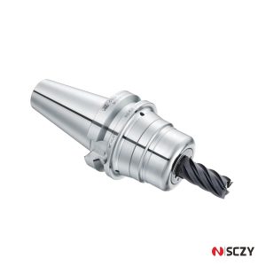
ER is the default for drills, small end mills, and anything that needs a wide clamping range. In BT30, ER16 and ER20 cover most of the work; ER25 is the practical ceiling. In BT40, ER32 is the workhorse and ER40 handles up to Ø26 mm shanks. Remember that ER holding force comes from nut torque, not from the taper, so nut condition and correct torque matter more than the catalogue’s clamping range.
Side lock and shell mill holders
For Weldon-shank cutters with heavy axial pull, a side lock holder is more secure than a collet. Shell mill and face mill arbors only make sense from BT40 upward if the cutter is larger than about Ø40 mm — a Ø50 mm face mill on BT30 is asking the interface to do something it was not designed for.
Tapping holders
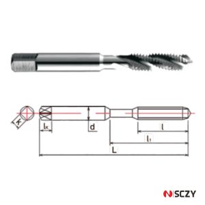
In BT30, tension-compression tapping holders are common because spindle synchronisation on compact machines is not always tight. In BT40, rigid or synchronous tapping is viable and faster, provided the machine’s sync error is small. Either way, the holder’s axial float and clutch setting decide whether you break taps, not the taper.
Pull Studs and Drawbar Setup
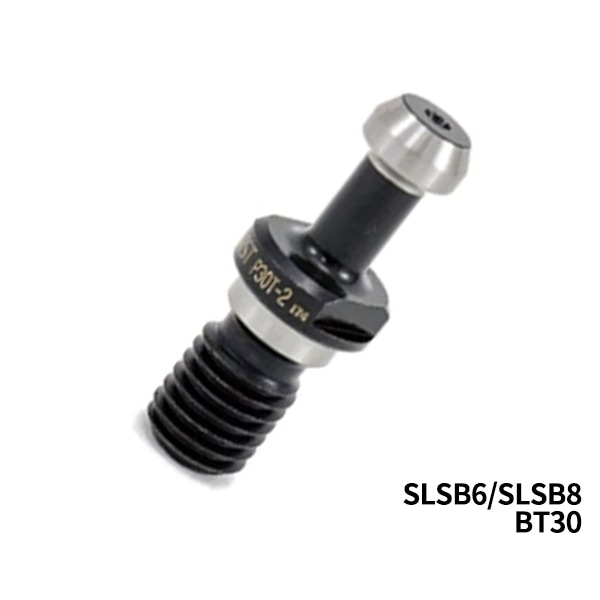
The pull stud is where most taper problems actually start. A BT30 stud is threaded M12, a BT40 stud M16, and the two are not interchangeable in any dimension — thread, neck length, flange angle, or overall length. Mixing them, or fitting a stud with the wrong neck length, changes how far the holder seats and quietly destroys taper contact.
Torque and centre-coolant
Typical installation torque is 25–35 N·m for M12 BT30 studs and 60–80 N·m for M16 BT40 studs. Under-torquing lets the stud back out and frets the spindle gripper; over-torquing stretches the thread and makes the stud impossible to remove without damage. If the machine runs through-spindle coolant, the stud needs the correct coolant bore and O-ring, and the O-ring is a wear item — a hardened or flattened ring is a coolant leak waiting to happen at the worst moment.
Drawbar force checks
Measure drawbar force at least annually, and any time a holder shows fretting or a part moves in Z. The reading tells you whether the problem is the holder or the spring stack — replacing holders to fix a weak drawbar is an expensive way to stay broken.
Practical Checks Before You Commit
Spindle nose and clearance
Check the distance from the spindle nose to the fixture at full Z travel. A BT40 holder with a large flange and a long gauge length eats clearance that a BT30 assembly would leave free — on compact machines this is often the deciding constraint, not stiffness.
Balance and speed rating
Any holder run above 10,000 rpm should be balance graded, and the holder’s speed rating must exceed the spindle’s maximum. A G6.3 holder at 20,000 rpm will vibrate no matter how good the taper is.
Storage and handling
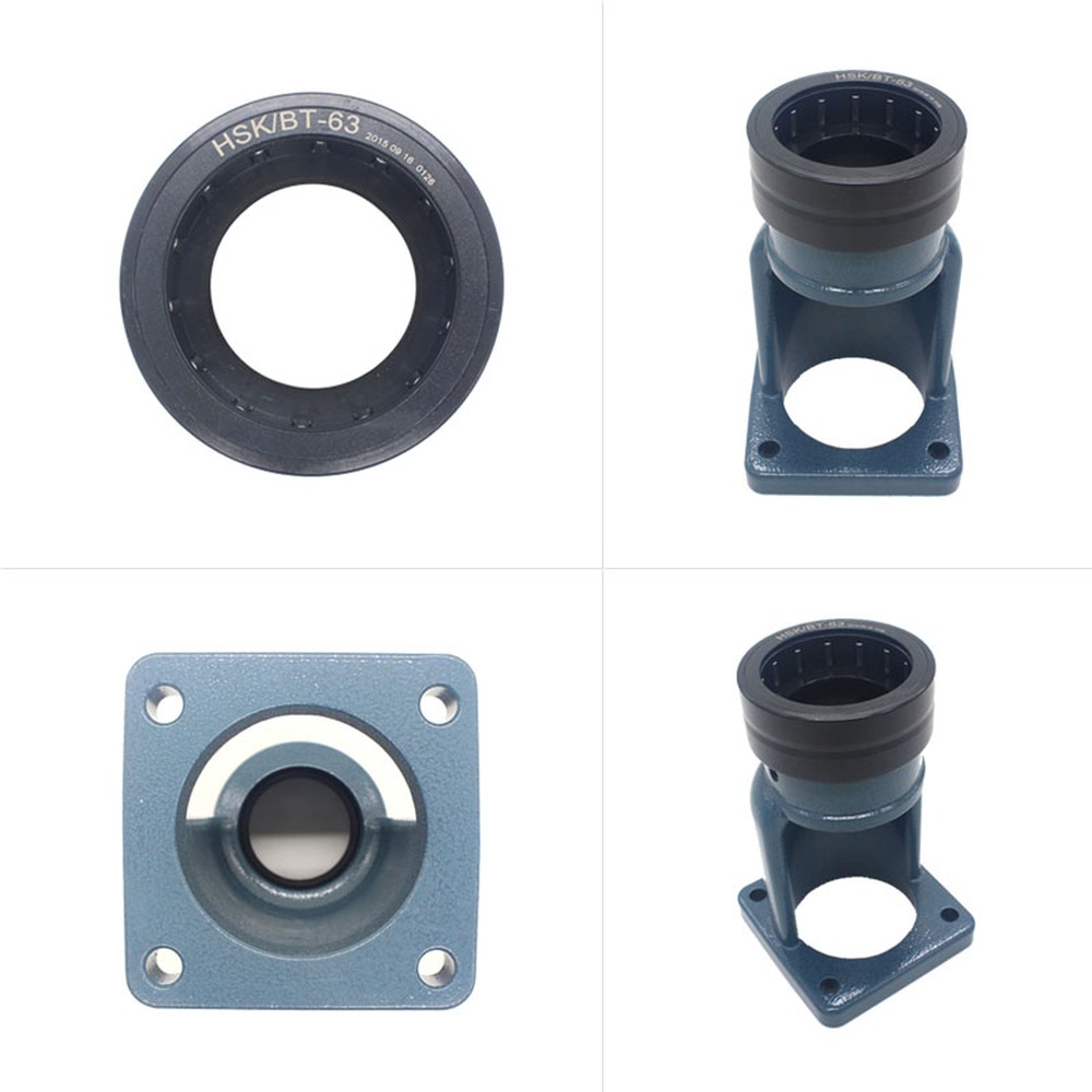
Taper contact percentage collapses when holders are stored on a bench where the taper can pick up dings. A dedicated rack, protective caps, and a wipe-down routine before every load cost very little and protect the interface that all your accuracy depends on.
Cost, Inventory, and the Honest Trade-Off
BT40 holders cost more per piece and force larger magazine investments, but they let one machine cover more work. BT30 holders are cheaper to duplicate and easier to keep in stock, which is why shops running families of small aluminium parts often own three of every holder they use. The answer follows part mix: if 80% of your work fits under Ø16 mm tools in non-ferrous material, BT30 is not a compromise but the efficient choice. If your work includes steel, one BT40 machine will replace two BT30 machines doing the same jobs badly.
Bringing It Together
Choosing between a BT30 tool holder and a BT40 holder is really a question about load: how much cutting force your process needs, how far you must reach, and how much mass your spindle can accelerate without losing accuracy. Match the taper to the load and both sizes perform predictably. Mismatch it and you will spend the life of the machine compensating for a decision made once.
If you are tooling up a new machine, replacing a worn holder set, or standardising holders across a mixed-taper shop floor, we can help you specify the right taper, gauge length, collet size, and pull stud for each operation. Send us your part drawings and machine list, and we will come back with a holder schedule you can order from — with the drawbar and balance requirements stated up front.