A thread forming tap does not cut a thread — it presses one. The tool is fluteless, its cross-section is lobed rather than round, and every revolution displaces material sideways into the flank instead of lifting a chip out of the hole. For shops tapping thousands of M3 to M8 holes in aluminium or mild steel, that removes the two failure modes behind most tapping scrap: chip packing in blind holes, and taps snapping at the bottom of a hole with nowhere left to put the chip. A thread forming tap also leaves a cold-worked grain structure with no interrupted cut, which is why forming is the default in high-volume aluminium work. It is not a universal swap, though: drill sizes change, torque roughly doubles, and some materials destroy the tap in a few dozen holes.
How a Thread Forming Tap Makes a Thread
Displacement instead of removal
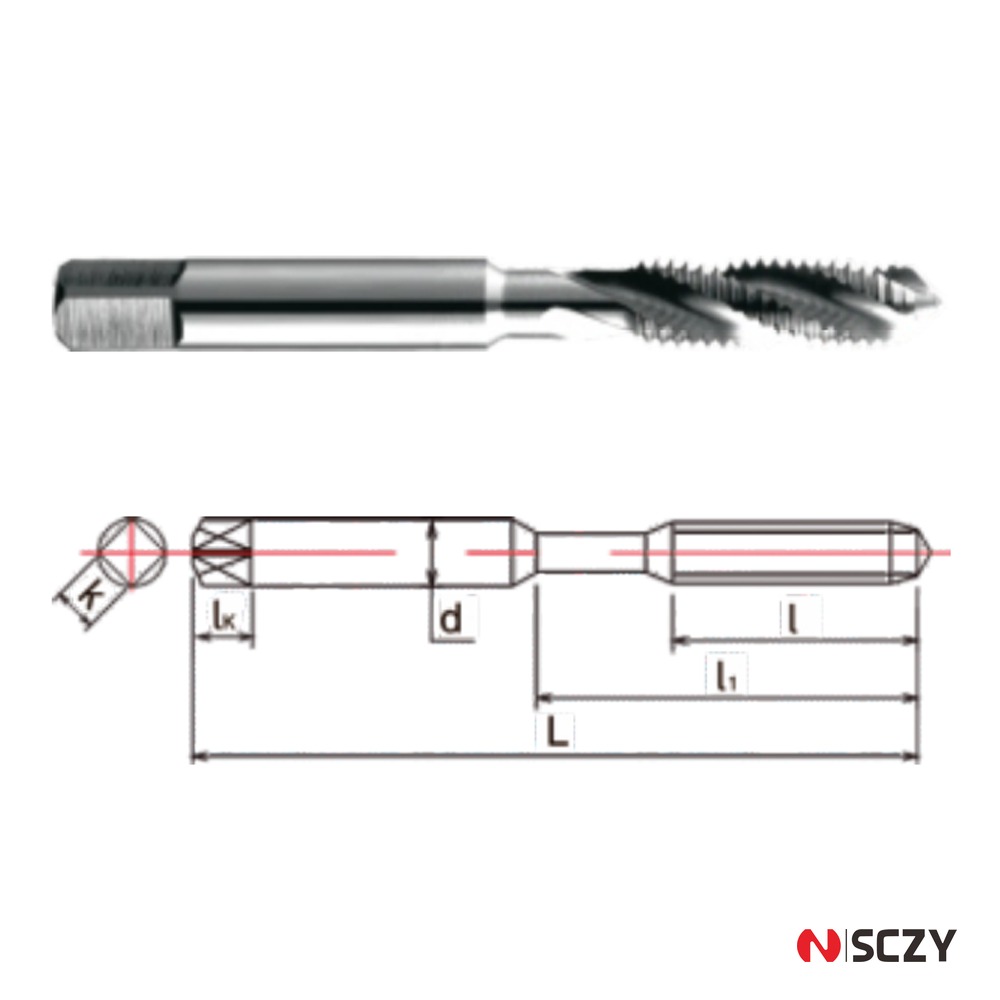
A cutting tap has flutes. The cutting edges shear material away, and the flute is a channel that has to carry that material out of the hole. A thread forming tap has no flutes at all. Its body is ground with a lobed profile — typically three to five lobes with narrow reliefs between them — and the lobes cold-work the bore wall into the thread form. There is no chip, so there is nothing to evacuate — which is why forming taps excel in blind holes and horizontal setups where chip evacuation is difficult.
What the lobes actually do
The lobe geometry is a compromise between forming efficiency and friction. More lobes spread the load over more contact points, lowering peak pressure and improving finish at the cost of higher torque. Fewer lobes concentrate the work, suiting softer, more ductile materials. The reliefs between lobes are not for chip clearance — they are lubrication channels and clearance for displaced material. That is why forming taps are far more sensitive to lubrication: starve the reliefs and the tap rubs instead of forming, torque climbs, and the lobes gall.
Where the displaced material goes
Nowhere new — it stays in the part. The starting hole must be larger than the minor diameter a cutting tap needs, because the material that becomes the crest has to come from somewhere. Keeping the old tap drill is the most common mistake when a shop switches to forming: an undersized hole raises torque sharply and usually ends with a broken tap.
Thread Forming Tap Drill Size: The Rule That Matters
Forming tap drill diameter is calculated from the nominal major diameter minus a fraction of the pitch:
Drill diameter ≈ major diameter − (0.4 to 0.5) × pitch
Most tap manufacturers publish charts built around 0.45 × pitch, which targets roughly 65 to 70 percent thread engagement. At that factor: M4 × 0.7 gives 3.69 mm (usually specified 3.7 mm), M5 × 0.8 gives 4.64 mm, M6 × 1.0 gives 5.55 mm, M8 × 1.25 gives 7.44 mm, and M10 × 1.5 gives 9.33 mm. Compare the cutting tap drills — 3.3, 4.2, 5.0, 6.8 and 8.5 mm — and the difference is obvious: forming needs a hole 0.3 to 0.8 mm larger on the same thread.
Why 65 to 70 percent engagement, not 75
Cutting taps are conventionally sized for about 75 percent engagement. Forming taps sit lower because the displaced material must fit into the flank without over-filling the crest, and an over-filled crest is what produces a thread that will not accept a GO gauge or that splits a thin wall. Cold work already improves fatigue behaviour, so the marginal strength from higher engagement is not worth the torque and breakage risk. If a drawing calls for a specific engagement, size the hole from the tap maker’s chart rather than a generic table — lobe geometry differs between brands.
Hole depth and the lead-in
A forming tap pushes material ahead of its lead. In a blind hole, drill deeper than you would for a cutting tap: thread depth plus three to four pitches, plus drill point allowance. If the hole is too shallow the displaced material has nowhere to go, the last threads come out malformed, and forming torque spikes exactly where the tap is weakest.
Forming Torque Is Higher — Plan for It
Cold forming takes more energy than shearing. Expect forming torque to run roughly 1.5 to 3 times that of a cutting tap in the same size and material, with the upper end applying to stainless and to work-hardening alloys. In practice this means three things.
The machine has to be able to deliver it
Small, high-speed drill-tap centres rated for M6 cutting taps may not have the torque margin for M6 forming. Check the torque curve at the actual tapping speed, not the rated peak. Undersized spindle power shows up as stalls at full engagement — exactly when the tap is most likely to break.
Synchronisation matters more, not less
Because forming has no chip clearance and a long engaged length, any feed mismatch between spindle and Z axis becomes axial load on the lobes. Rigid tapping with an encoder-synchronised spindle is preferred. On machines without spindle feedback a tension-compression holder absorbs the mismatch, but it must be pre-loaded so the tap is neutral at engagement, not pulling against the spring through the whole cut. Excessive axial float on a forming tap produces pitch errors that only show up at the gauge station.
Lubrication is a process parameter
Treat lubricant as tooling, not coolant. Forming aluminium dry or with a lean flood often galls within a few hundred holes. Internal coolant through the tap, or a dedicated tapping lubricant applied at the hole, gives markedly longer life.
Thread Forming vs Cutting Taps: A Practical Comparison
| Factor | Thread forming tap | Thread cutting tap |
|---|---|---|
| Chip generation | None — material is displaced | Chips must be evacuated by flutes |
| Tap drill, M6 × 1.0 | About 5.5 mm | 5.0 mm |
| Thread engagement target | 65–70% | About 75% |
| Torque vs cutting tap | 1.5–3× higher | Baseline |
| Thread strength | Cold-worked flanks, better fatigue resistance | Cut flanks, grain structure interrupted |
| Blind hole behaviour | Excellent — no chip to pack | Risk of chip packing and tap breakage |
| Best materials | Aluminium, copper, brass, low-carbon and free-machining steel | Almost everything, including brittle and hard materials |
| Poor materials | Cast iron, hardened steel, titanium, work-hardening stainless | Cast iron and hardened steel are routine work |
| Hole tolerance sensitivity | High — hole size sets thread size directly | Moderate — the tap cuts its own size within limits |
| Thin-wall parts | Hoop stress can bulge the wall | Lower radial load |
| Lubrication demand | High | Moderate |
| Tool life in aluminium | Very long, often 5–10× cutting taps | Limited by chip welding on edges |
Materials: Where Forming Wins and Where It Fails
Where it wins
Ductile materials with reasonable elongation are the natural home. Aluminium alloys, particularly die-cast and wrought 6000-series, form beautifully, and the absence of chips eliminates the smeared buildup that shortens cutting tap life. Copper and most brasses form well, as do low-carbon and free-machining steels up to roughly 300 HB. Forming taps in these materials often run several times the hole count of a cutting tap, with a stronger fatigue-resistant thread because grain flow follows the flank instead of being severed by it.
Where it fails
Cast iron is the classic wrong answer: it is brittle, so instead of flowing it crumbles and the thread comes out ragged. Hardened and high-alloy tool steels exceed what the lobes can displace. Titanium and austenitic stainless are marginal — both work-harden ahead of the lobe, so torque climbs until something gives. If you must form in 304 or 316, keep surface speed low, lubricate generously, and expect far shorter life than in aluminium. Thin walls need their own caution: the radial load pushes outward, and a wall under roughly 1.5 times the thread diameter can bulge enough to lose roundness even when the thread gauges correctly.
Common Failure Modes and What They Tell You
Tap breaks in a blind hole
Almost always an undersized hole or insufficient depth. Check the actual drilled diameter with a pin gauge rather than trusting the drill’s nominal size — a worn drill or reground point can easily drill 0.1 mm small, enough to double forming torque on a small thread. Verify hole depth against thread depth plus three to four pitches.
Thread will not accept the GO gauge
Either the hole is oversized, usually from a drill that wandered or a spot drill that opened the start, or the part is thin-walled and sprang back after the tap withdrew. In aluminium, high speed with poor lubrication also tears the crest so it gauges undersize on the flanks.
Galling and lobe pickup
Adhesive wear on the lobes in aluminium and copper. Reduce surface speed, increase lubricant delivery, and check that the reliefs are not packed with compacted material.
Chipped lobes
Hard spots, cast skin, or an interrupted hole. If the surface is abrasive or already work-hardened, form the thread after removing the skin, or use a cutting tap for that feature.
Holding the Tap: Rigid Beats Floating Where You Have the Choice
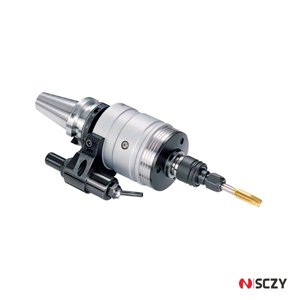
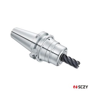
Tool holding is where forming taps are most often let down. On a machine with synchronised rigid tapping, hold the tap in a high-accuracy ER collet chuck with a collet sized to the tap shank, and check runout at the shank — 0.02 mm TIR or better, because eccentricity loads one lobe harder than the rest. Without spindle feedback, use a tension-compression tap holder set so the tap is neutral at engagement rather than pulling against the spring through the whole cut.
A Short Selection Checklist
- Material first. Ductile and under roughly 300 HB — proceed. Cast iron, hardened steel, titanium, 300-series stainless — stay with cutting taps.
- Recalculate the drill. Nominal diameter minus 0.45 × pitch, verified against the tap maker’s chart.
- Add depth. Thread depth plus three to four pitches, plus drill point.
- Check torque margin at the tapping speed you intend to run.
- Confirm synchronisation. Rigid tapping if available; pre-loaded tension-compression holder if not.
- Treat lubricant as tooling, especially in aluminium.
- Gauge the first parts with GO/NO-GO plug gauges, and re-check after any drill change.
The Bottom Line
A thread forming tap is the right default for high-volume threads in aluminium, copper, brass and mild steel, and the wrong tool for cast iron, hardened steel and thin walls. The switch is not a drop-in substitution: drill sizes move by 0.3 to 0.8 mm, torque roughly doubles, and lubrication becomes a process parameter. Get those three right and forming taps will run for thousands of holes without a chip in sight.
If you are choosing between forming and cutting for a specific material and thread size, our team can match the tap, holder and drill to your machine’s torque and synchronisation capability. Talk to the SCZY technical team with your material, thread specification and spindle data, and we will come back with a concrete recommendation rather than a catalogue page.
GET A QUOTE
Looking for thread forming solutions for your production?
Explore our product range or send us your requirements. Our team will be glad to review your inquiry.