A sine magnetic chuck does one job: it holds a flat steel part at a known angle so the wheel can grind that angle true. It is the least glamorous tool in a grinding department and one of the most useful, because the alternative — clamping a part to a tilting vise and hoping the pointer is honest — usually costs you a second setup and a re-check with an indicator. On a sine magnetic chuck, the angle comes from geometry rather than from a scale, and geometry does not drift between shifts.
This guide covers how the angle is generated, how to do the stack height math at the machine, where the magnetic version beats clamps and where it cannot be used at all.
What a sine magnetic chuck actually is
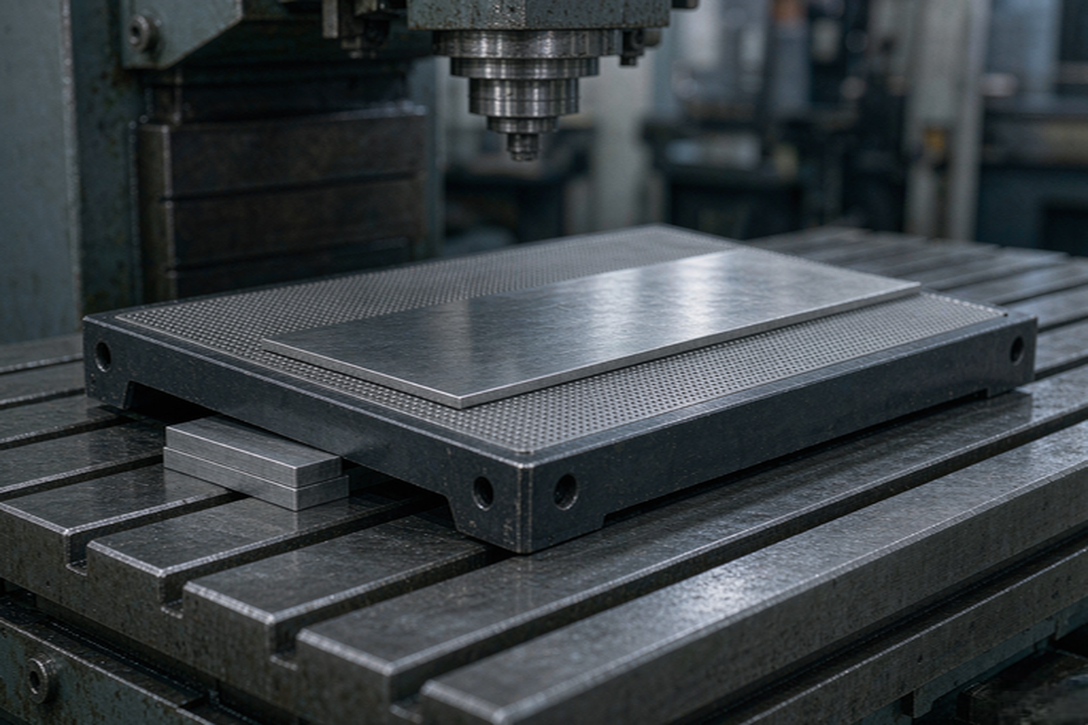
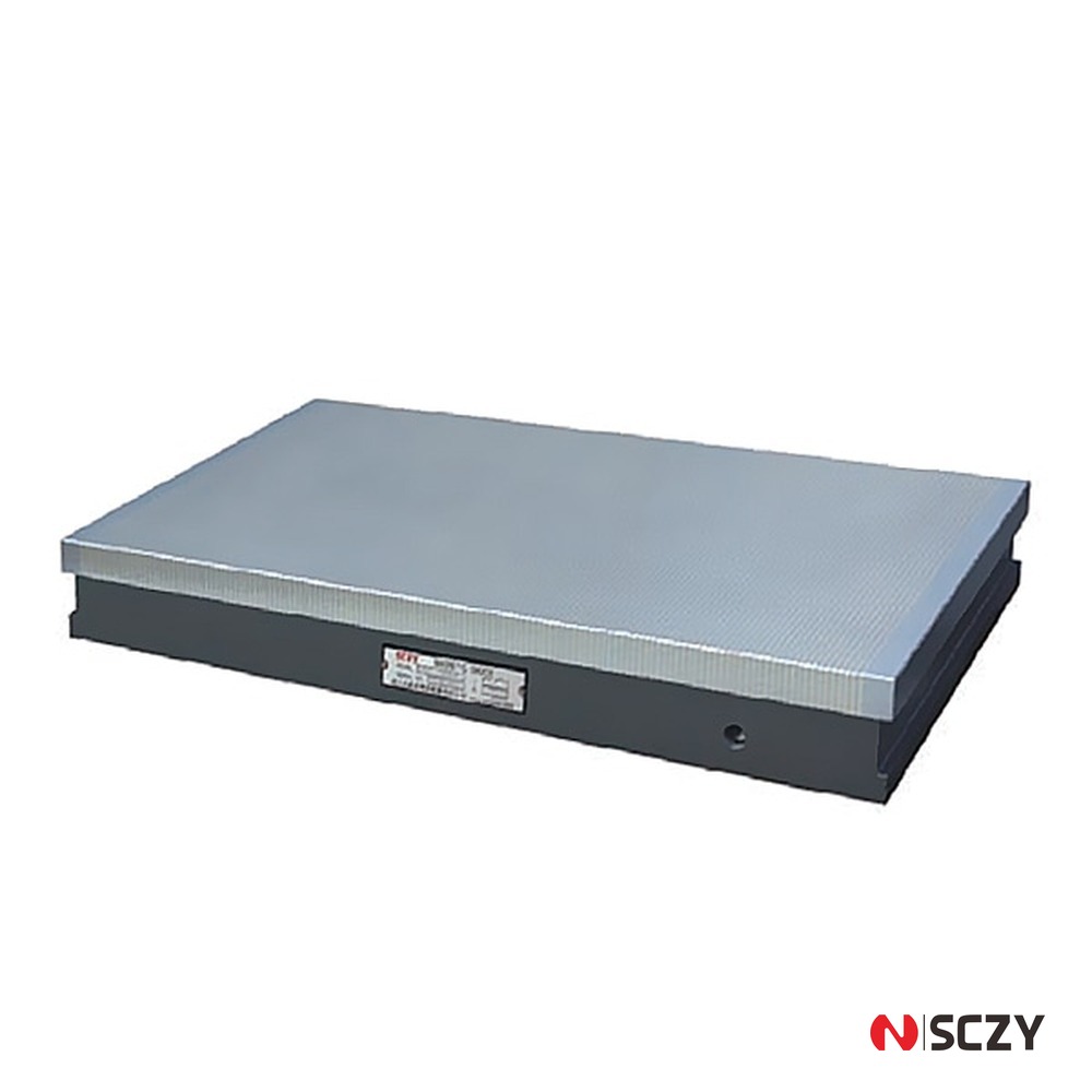
The body is a base plate with two hardened steel rolls set a fixed distance apart, and a top plate that rests on those rolls. One edge of the top plate is hinged on the first roll. The other edge is lifted by a stack of gauge blocks placed between the base and the underside of the plate. The part sits on the top plate, which is a magnetic pole plate — either electromagnetic or electro-permanent — so it is held flat against the inclined face without clamps.
That last point is the whole reason the tool exists. A clamp applies force at two or three points and bends the part; a magnetic face applies pressure across the entire footprint. On a 3 mm plate that must be ground to 0.01 mm flatness, the difference is not subtle.
The geometry in one formula
The angle is set by the height of the stack: sin θ = h / L, where h is the gauge block stack height and L is the center distance between the two rolls — not the length of the plate, not the distance between the roll edges. A 100 mm sine chuck with a 20.791 mm stack gives 12.00°. A 200 mm chuck with the same stack gives 5.96°, which is why the L value has to be read off the nameplate rather than assumed. Working backwards is just as easy: required stack h = L × sin θ. On a 100 mm chuck, 15° needs 25.882 mm of gauge blocks, and 30° needs exactly 50.000 mm.
Single-roll and two-roll designs
Most chucks hinge on one roll and are lifted at the other. A two-roll arrangement under the lifted edge keeps the plate supported across its width instead of rocking on a line, and is worth the extra cost on wide plates.
Doing the angle math at the machine
Nobody should be calculating sines beside a grinder with a phone in one hand. Print the table for your L value once, tape it inside the cabinet, and work from it.
Work from the stack, not from the scale
Set the stack with a height gauge on a surface plate, wring the blocks, and check the total with a micrometer before it goes under the plate. A 0.01 mm error in stack height on a 100 mm chuck is roughly 0.36 arcmin of angle error at 15° and about 0.5 arcmin at 45° — the same error costs more angle the steeper you go, because the cosine in the denominator shrinks.
Compound angles need a second axis
Rotating a tilted single-axis chuck on the machine table does not produce the compound angle most drawings ask for. For 8° in one plane and 12° in another, use a two-axis (compound) sine chuck, or set the part rotated on the chuck and calculate the stack from the compound-angle formulas rather than adding the two angles together. Adding them is the most common mistake in this setup, and it shows up as a taper that grows along the part.
Check the angle on the part, not the fixture
Indicate the ground face after the first pass, not the chuck face. A perfectly set chuck can still leave the part 2 arcmin off because a chip was trapped between plate and workpiece.
Sine plate vs sine magnetic chuck vs tilting vise
The four common ways to grind an angle are not interchangeable; the choice comes down to part thickness, material and batch size.
| Setup | How the part is held | Practical angle range | Typical angle error | Time to change angle | Best for | Weak point |
|---|---|---|---|---|---|---|
| Sine plate with clamps | Clamped to a hinged plate | 0–60° | 1–2 arcmin | 5–15 min | One-offs, odd shapes, non-magnetic parts | Clamp deflection, jaw marks |
| Sine magnetic chuck, electromagnetic | Magnetic face, full contact | 0–45° | 0.5–1 arcmin | 2–6 min | Thin flat steel, batch work | Coil heat, needs demagnetizing |
| Sine magnetic chuck, electro-permanent | Magnetic face, permanent magnets switched by pulse | 0–45° | 0.5–1 arcmin | 2–6 min | Small parts, long cycles, no heat rise | Higher purchase cost |
| Tilting or swivel vise | Vise jaws | 0–90° | 5–15 arcmin | 1–3 min | Blocky parts, loose tolerances | Jaw lift, scale error |
| Angle plates and wedges | Bolted fixture | Fixed angles | 1–5 arcmin | Long | Production at one fixed angle | Not adjustable |
Where the magnetic version wins — and where it fails
Thin, flat parts that clamps would distort
Anything under about 6 mm thick, and anything where flatness is called out tighter than 0.02 mm, is magnetic-chuck work: the part is supported over its whole area, with no elastic springback when the clamps come off, because there were no clamps.
Non-magnetic workpieces simply do not work
Aluminum, brass, copper, titanium and austenitic stainless such as 304 have no meaningful response to a magnetic field — the part will slide on the first spark. Ferritic grades such as 430 do hold. For non-magnetic parts the choices are a vacuum chuck, a dovetail fixture, or a mechanical sine plate with clamps.
Holding force on an inclined face
A catalog number is the normal holding force on a flat, fully covered pole face. Tilting the face splits that force in two, and only one component does useful work.
The normal and shear split
At angle θ, the force pressing the part against the face is F × cos θ, and the force trying to slide it down the incline is F × sin θ. At 15° that is 96.6 percent normal and 25.9 percent shear. At 30° it is 86.6 percent and 50 percent. At 45° the shear component reaches 70.7 percent of the rated force — a steep setting is not just harder to reach, it is a fundamentally weaker hold.
Surface grinding forces are small, typically well under 100 N on a light pass, so a chuck rated at 120 N/cm² on a 100 cm² face has enormous margin. What actually causes trouble is the wheel climb on a down-grinding pass, coolant drag, and the operator’s hand during loading. Keep the estimated working load under about 20 percent of the available holding force at the set angle, and add a stop block on the low edge above 30°.
Pole pitch and small parts
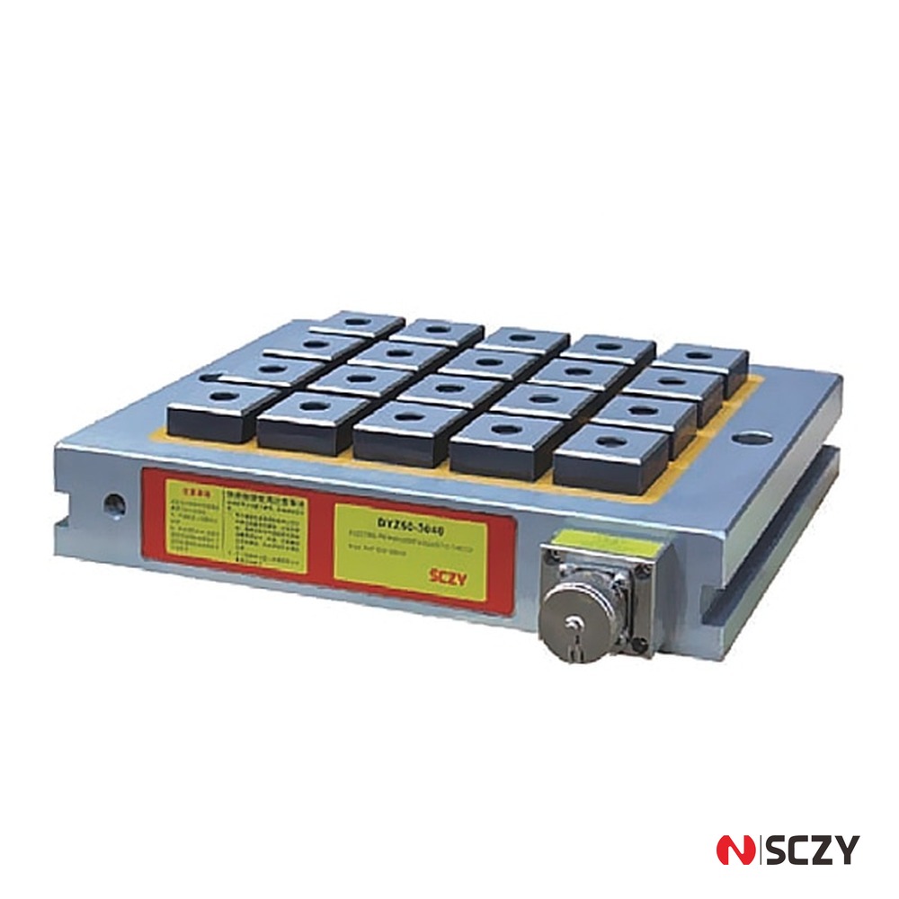
Holding force is generated at the poles, so a part that straddles only one or two poles gets a fraction of the rated force. Fine-pole chucks use a pole pitch in the region of 0.5 to 1.5 mm so that small parts and thin strips bridge several poles. Under 10 mm wide, pole pitch matters more than the headline force rating — a coarse chuck with a higher rating can hold less on a small part than a fine-pole chuck with a lower one. Our guide to fine pole magnetic chucks and pole pitch goes deeper.
What actually limits your angle accuracy
Roller center distance tolerance
L is the reference the whole calculation depends on. If the actual center distance is 100.03 mm instead of 100.00 mm, every angle you set is off by roughly 1 arcmin at 30°, and no amount of careful gauge block work will recover it. Ask for the measured L value with the chuck, not just the nominal size.
Gauge block stack and wringing
A stack of six blocks wrung together is fine; a stack of six with a chip between two of them is not. Wring each interface and keep the stack under about 100 mm — a 90 mm stack on a 100 mm chuck is a slender column that can lean under the plate’s weight.
Plate flatness, wear and residual magnetism
The top plate is a wear item. Ground every few years it stays flat; neglected it dishes in the middle and the part rocks. Residual magnetism is the second wear item: an electromagnetic chuck switched off without a demagnetizing cycle leaves the part magnetized, chips cling to the face, and the next part never sits fully flat. Electro-permanent chucks leave almost nothing behind, which is why they suit long grinding cycles and parts that go straight into cleaning.
A setup routine that repeats
- Wipe the machine table, the chuck base and the chuck face. Stone any burrs on the back face of the part.
- Wring the gauge block stack to the calculated height and verify it with a micrometer.
- Set the stack under the lifted edge, lower the plate gently, and clamp the hinge side only to the specified torque.
- Indicate the chuck face along the grinding direction and confirm the actual angle before loading a part.
- Load the part, switch on, and check that it cannot be moved by hand at the low edge.
- Grind a light first pass, indicate the ground face, and correct if needed. Switch off, run the demagnetizing cycle, and lift the part with a plastic wedge.
Specification checklist before you buy
- Footprint against your table. A chuck that overhangs cannot be indicated properly and will not repeat.
- L value and its tolerance. Ask for the measured center distance and the angle accuracy guaranteed at 15° and 30°.
- Pole pitch. Under 2 mm for small or thin parts; coarse only for large blocks.
- Holding force per cm² at the rated pole face. Compare like with like — some catalogs quote peak force at zero air gap, which no real part achieves.
- Electromagnetic or electro-permanent. Coil heat and demagnetizing cycles versus purchase price.
- Coolant and swarf protection, height and weight. The controller and cable entry fail first in a grinding room, and a 200 mm chuck eats into wheel clearance.
Matching the chuck to the work
The right sine magnetic chuck is the smallest one that covers the largest part you regularly grind, with a measured L value you trust, a pole pitch fine enough for your smallest part, and a controller that demagnetizes properly. Everything else — the badge, the paint, the catalog photography — does not change the angle on the part.
If you are setting up a grinding cell and need to match chucks and angle fixtures to specific parts, contact SCZY with your part sizes, required angles and table dimensions. For a wider comparison of magnetic workholding types, see our magnetic chuck buyers guide; for parts that magnetism cannot hold, the vacuum chuck comparison covers the alternatives.
Looking for a suitable tooling solution? Explore our product range or contact our team for a quotation.