TL;DR — the short version
- Below 12,000 RPM, BT40 is not a compromise. It is the right answer. It costs less, tolerates crashes better, and every presetting station you already own fits it.
- Above 15,000 RPM, centrifugal force expands the spindle bore and pulls the BT holder inward — Z-axis shifts of 0.02–0.05 mm mid-cut. HSK-A63 clamps against the spindle face, so the effect disappears.
- Typical tip runout: BT40 at 3–6 μm, HSK-A63 at 1–3 μm at comparable taper accuracy. That gap is worth roughly 20–30% of carbide tool life on finishing passes.
- Most shops don’t need to “switch.” They need to split the two interfaces by spindle, not by preference — and that split has a specific rule (see Section 4).
If you have ever stood in front of a tool crib with two machines running different spindle tapers and thought “why do we have both of these?” — you are not alone. And the answer usually isn’t bad planning. It’s that the BT machine came first, the HSK machine came later with a higher-speed spindle, and nobody ever wrote down which jobs belong on which.
Most comparisons of BT40 vs HSK-A63 frame it as a contest: which interface is better? That framing is not very useful, because there is no universal winner. The question that actually matters for a working shop is narrower and more practical:
On this machine, cutting this part, at this speed — which interface should be in the spindle, and what does it cost me to be wrong?
This article answers that from the floor up. No brand loyalty, because in most shops the decision is made per-spindle anyway.
1. How each interface actually holds the tool
The difference that matters isn’t the shape. It’s where the locating happens.
BT40 — the taper does all the work
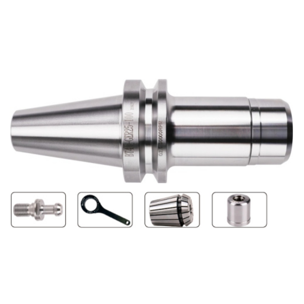
BT40 (MAS 403 BT, standardised as ISO 7388-1) uses a 7:24 taper. The drawbar pulls the holder shank up into a matching taper in the spindle nose. That single taper surface has to do three jobs simultaneously:
- Centre the holder radially
- Transmit torque through friction
- Resist the cutting forces trying to push the holder sideways
Torque transmission is entirely frictional. Which means the amount of grip depends on how hard you pull — and on how good the taper contact is. A properly ground AT3 holder should show 80%+ contact when checked with marking compound. Anything below that and you are transmitting torque through a fraction of the surface you think you are.
This design is simple, cheap, extremely robust, and — importantly — it is the reason BT tolerates abuse better than anything else on the market. A crash usually costs you a set screw or a replaceable collet, not a $400 holder.
HSK-A63 — the taper centres, the face locates
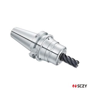
HSK-A63 (ISO 12164 / DIN 69893, “hollow shank taper”) splits those jobs across two surfaces, and that is the whole trick:
- The 1:10 hollow taper provides radial centring only.
- Internal clamping wedges expand inside the hollow shank and pull the holder flange against the spindle face. Axial position is set by metal-to-metal face contact, not by how far up the taper it crept.
Why does that matter at speed? Because centrifugal force tightens HSK instead of loosening it. The faster it spins, the harder those wedges are thrown outward, and the tighter the flange locks to the face. It is self-reinforcing precisely where BT is self-defeating.
2. The numbers, side by side
Figures below are typical values for AT3 taper accuracy holders of comparable quality, measured at roughly 2.5× diameter projection. Individual holders vary; cheap holders vary a lot more.
| Parameter | BT40 (ISO 7388-1) | HSK-A63 (ISO 12164) |
|---|---|---|
| Taper ratio | 7:24 | 1:10 (hollow) |
| Locating surface | Taper only | Taper + spindle face (dual) |
| Practical RPM ceiling | ~12,000–15,000 | 25,000+ (balance-dependent) |
| Tip runout, typical | 3–6 μm | 1–3 μm |
| Z-axis drift above 15k RPM | 0.02–0.05 mm | Under 0.005 mm |
| Torque transmission | Friction only | Mechanical + friction |
| Crash tolerance | High — replaceable consumables | Lower — body damage likely |
| Holder cost, relative | Baseline | Approx. 1.2–1.8× |
| Retrofit required | None | Often needs new spindle + gripper |
The two rows that decide most arguments are the runout row and the RPM ceiling row. Everything else is downstream of them.
3. What centrifugal force actually does to BT40
This is the part that trips people up, because it is invisible on the bench.
A BT40 holder you measure at zero RPM sits at maybe 3 μm runout. Put it in a spindle at 15,000 RPM and two things happen:
First, the spindle bore grows. The spindle nose is steel spinning very fast. Centrifugal force expands it — typically 15–25 μm on diameter at 20,000 RPM. The tool holder shank, held inside that bore, is subject to the same rotation but is far more constrained, so it does not grow to match.
Second, the holder gets pulled deeper. The drawbar has thousands of newtons of preload on it, and it now has room to pull the shank further up the taper, because the bore opened up around it. So the holder moves — 0.02–0.05 mm along Z, typically.
Now put that in context of an actual cut. If you are finishing with 0.10 mm of stock left on the wall, a 0.03 mm shift is a 30% error in your depth of cut. That is not a tolerance problem. That is a scrapped part.
A note worth keeping taped to the wall: this drift is repeatable, not random — so it often survives a test cut and then shows up as inconsistent wall thickness once the part heats up and speeds settle. Shops spend weeks blaming the tool.
Why HSK doesn’t do this
Because the holder’s Z position is set by the flange sitting flat against the spindle face, and no amount of radial expansion changes where that face is. The hollow shank is designed to flex slightly inward with the expanding bore, maintaining taper contact — and the wedges tighten as speed rises.
4. The three thresholds that decide it
Forget preference. Three measurable things settle this.
Threshold 1: Spindle speed
| Your spindle max | Answer |
|---|---|
| Under 10,000 RPM | BT40. Don’t overthink it. |
| 10,000–15,000 RPM | BT40 still works; start measuring if you see unexplained finish variation. |
| Above 15,000 RPM | HSK-A63 (or HSK-E/F depending on form). BT is now costing you money. |
| Above 30,000 RPM | HSK-E40 or F63 territory. Standard HSK-A is not appropriate. |
12,000 RPM is the practical line. Not a hard limit — BT physically works above it — but above that line the Z-drift starts competing with your tolerances.
Threshold 2: Tool projection length
This one gets ignored, and it is often the deciding factor on older machines.
Runout isn’t a property of the holder alone — it’s a property of the holder plus everything hanging off it. A 3 μm error at the holder nose becomes considerably larger at the tip of a long-reach holder.
Good working rule: for projections beyond roughly 4× diameter, prioritise runout over everything else. If you are running a 100 mm extension on a BT40 at 8,000 RPM, your effective runout may already be worse than an HSK setup at three times the speed.
Threshold 3: What you’re actually cutting
| Situation | Lean toward |
|---|---|
| Roughing steel and stainless, big radial cuts | BT40 — stiffness and crash tolerance matter more than 3 μm |
| Finishing aluminium at high RPM | HSK-A63 — this is what it’s for |
| Hardened tool steel finishing | HSK-A63 — predictable edge load keeps the edge alive |
| Job shop, constant changeovers, mixed operator skill | BT40 — consumables are cheap, mistakes are survivable |
| Lights-out / unattended runs | HSK-A63 — you cannot babysit the tool |
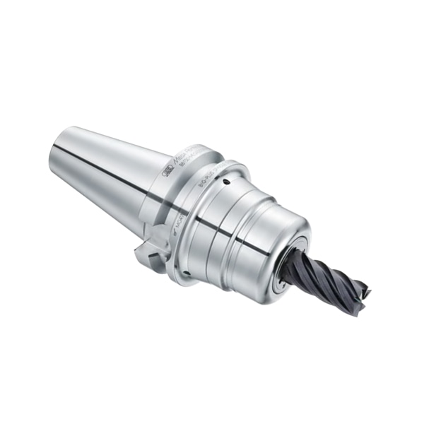
5. The real problem: running both
Here is where this article parts company with most comparisons.
The theoretical question is “which interface is better.” The actual question on most floors is “we already own both — how do we stop wasting money on the seam?”
Shops running mixed interfaces usually haemorrhage money in four specific places:
1. Duplicate tooling across interfaces. The same 12 mm end mill exists as a BT40 assembly and an HSK-A63 assembly, both preset, both taking up crib space. When it’s genuinely needed for both machines, fine. Often it isn’t — nobody audited it.
2. Buying HSK holders and running them at 8,000 RPM. The most common pure waste. The premium buys you precision you cannot use at that speed. If the machine maxes at 8,000, buy BT.
3. Buying BT holders and running them at 18,000 RPM. The mirror-image mistake, and far more expensive — you pay in carbide, scrapped parts, and spindle bearing wear.
4. Skipping presetting discipline on the mixed floor. A mixed crib means two sets of pull studs, two gauge lengths, two balance requirements. This is where most of the hidden cost lives.
A workable split rule
Instead of letting each job find its own answer, assign by spindle and hold the line:
- Every tool that touches a spindle above 15,000 RPM gets HSK. No exceptions, no “but this one is just a roughing pass.”
- Every tool below 10,000 RPM stays BT. Cheaper to buy, cheaper to replace after a crash.
- The 10,000–15,000 RPM band gets audited job by job — projection length and finish requirement decide it. This band is where the genuine judgement calls live, and it should be reviewed yearly, not never.
Write the split down. Put it in the setup sheet template. The value isn’t the rule itself — it’s that new tooling gets ordered against it instead of against whoever is standing at the machine that day.
6. What switching actually costs
The comparison table above makes HSK look like a clear upgrade. It usually isn’t, because the holder is rarely the expensive part of the decision.
To move a machine from BT40 to HSK-A63 you typically need:
- New holders across your existing library — the largest single line item
- A spindle change or machineside retrofit — if the machine wasn’t ordered with an HSK option
- Pull studs / retention knobs — HSK uses a completely different gripper geometry
- New presetter adapters and gauges — your existing ones likely don’t fit
- Possibly new tool measurement routines in the control
Against that, the benefits:
- Tool life on finishing operations typically improves 20–30% — that’s the runout reduction talking, not better carbide
- More consistent Z-depth above the 12,000 RPM line
- Better surface finish because there is less tip vibration
A common rule of thumb for the tool life loss side of this: every additional 0.0001″ (roughly 2.5 μm) of runout costs you roughly 10% of cutting tool life. Whether or not you take the exact figure literally, the direction is well established and it compounds fast at speed.
So the honest test is this: add up your annual carbide spend on the finishing operations running above 12,000 RPM. If the tooling savings don’t pay back the retrofit inside about 12–18 months, don’t do it. On a single low-RPM machine, upgrading makes no sense at all. On a cell running three shifts of high-speed aluminium work, the payback can be under six months.
Neither answer is wrong. It depends entirely on where your RPM actually sits — which is why the audit below starts there, not with a product catalogue.
7. A 4-step audit you can run this week
You don’t need new software. You need an afternoon and a dial indicator.
Step 1 — Make a spindle inventory. Every machine, its interface, its max RPM, and what it actually runs at on your top five jobs. Most shops discover at least one machine was ordered with an HSK taper and never used as one.
Step 2 — Sort jobs by spindle speed, not by part number. Everything above 15,000 RPM goes in one pile, everything below 10,000 in another. The middle band is your review list.
Step 3 — Check taper contact before you blame anything else. Thin coat of marking compound on the spindle taper, insert with correct drawbar force, remove, look at the pattern. 80%+ contact across the full taper length is the target. Contact bunched at the big end means a bell-mouthed spindle — no holder is going to fix that. Contact only at the small end means the holder is bottoming out.
Step 4 — Measure runout at operating speed if you can. Not on the bench. A non-contact probe on a running spindle tells you what the tool actually sees. Anything over about 5 μm at rated max RPM is a problem regardless of interface.
FAQ
At what RPM should I actually switch from BT40 to HSK?
12,000 RPM is the practical threshold. Below it, BT40’s cost and crash tolerance win comfortably. Above it, spindle bore expansion starts causing measurable Z-axis shift, and HSK-A63 is the better tool. Between 10,000 and 15,000, decide based on your projection length and finish requirements.
How much of a runout difference is there really?
Typically 3–6 μm for a good BT40 versus 1–3 μm for an HSK-A63, both at AT3 accuracy. But note that both numbers get worse with tool projection — a long-reach assembly can double the effective error at the tip, which is why projection length sometimes decides this before RPM does.
Can I just use an adapter to run BT40 tooling in an HSK spindle?
Technically yes; practically, avoid it. Every adapter adds its own tolerances — commonly 8–15 μm of cumulative runout — which erases most of what you paid for with the HSK spindle. Adapters make sense for one-off jobs, not production.
Which survives a crash better?
BT40, clearly. A mishap usually costs a set screw or replaceable collet. HSK bodies tend to take permanent damage, and a bell-mouthed bore means a new holder. If your floor has trainees or frequent crashes, that difference is worth real money.
What taper accuracy should I specify?
AT3 minimum for both interfaces. Lower grades or unspecified “standard accuracy” holders commonly show 8–15 μm runout, which is unacceptable for finishing work no matter which interface you choose. Accuracy class matters more than the interface argument on a mid-range machine.
Do I need to worry about tool holder balance?
Above about 15,000 RPM, yes. Specify balancing to G2.5 at operating speed per ISO 1940-1. G6.3 (a common default) generates roughly 2.5× the unbalance force, and that force goes straight into your spindle bearings. Note that unbalance force rises with the square of RPM, so a holder that’s fine at 8,000 may be destructive at 20,000.
A word on where SCZY fits
Most interface guides are written by somebody selling one interface. That shapes the conclusion more than the engineering does.
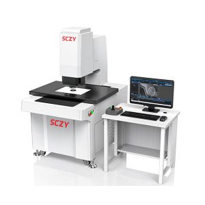
SCZY works the other way around. We are a technical sourcing partner based in Dongguan, working with a vetted group of factories across BT, BBT, HSK and ISO tool holders — plus collet chucks, workholding, and the metrology instruments needed to check any of it. That means when you ask “should this machine be BT or HSK,” there is no inventory bias in the answer.
In practice that usually takes one of three forms:
- Mixed-interface sourcing in one shipment. Consolidating BT and HSK requirements from multiple factories into single shipments, so adding HSK capacity doesn’t mean opening three new supplier relationships.
- Small quantities. Testing HSK-A63 on one cell shouldn’t require committing to a full tool library. Sample quantities for evaluation are normal, not a special favour.
- Specification review before you buy. Send us the spindle speeds and the jobs, and we’ll tell you where BT is genuinely the right answer. Sometimes that means selling you less, and that’s fine.
GET A QUOTE
Looking for the right tool holder interface for your machine?
Explore our product range or send us your requirements. Our team will be glad to review your inquiry.