Swapping a manual chuck for a pneumatic chuck for CNC machining is one of the fastest productivity wins available to a small or mid-size shop. A pneumatic chuck clamps and releases with a button press, holds consistent force on every part, and does not rely on the operator’s arm strength at 3 p.m. on a Friday. That sounds simple, but buyers routinely overpay for clamping force they don’t need, undersize their air supply, or pick a single-station layout that throttles their spindle utilization. This guide walks through how these chucks actually work, what the specifications mean, and how to decide between single-chuck and multi-station layouts for your parts.
How a Pneumatic Chuck Actually Works
Unlike a manual chuck that you tighten with a chuck key, a pneumatic chuck uses compressed air to actuate the jaws. When air is supplied, a piston inside the chuck body drives a jaw-opening mechanism — typically a scroll plate, wedge hook, or lever linkage — that moves the jaws inward onto the workpiece. Release the air, and springs or reverse air pressure open the jaws again.
The Force Math Behind a 10,000 N Chuck
Manufacturers quote clamping force in newtons or kilogram-force at a stated air pressure. Our SC-G0003 and SC-G0006 series, for example, are rated at 10,000 N with 6 bar (about 87 psi) supply pressure. Two things matter when you read these numbers:
- Force is pressure-dependent. If your shop line only delivers 4.5 bar at the machine after losses through fittings and a throttled FRL unit, you will not see the rated 10,000 N. A good rule of thumb: verify pressure at the chuck inlet, not at the compressor.
- Rated force is not grip force on your part. Friction in the scroll or wedge mechanism and jaw guides consumes some of the piston force. Compare chucks using the manufacturer’s stated jaw force at a common pressure, and ask for the force-vs-pressure curve if the datasheet doesn’t include one.
Why Consistent Clamping Beats Strong Clamping
For most small aluminum and steel parts, 10,000 N is plenty. What separates a quality pneumatic chuck from a cheap one is repeatability: the same jaw position, the same force, part after part. That consistency is what lets you push feeds confidently and trust that a work-offset saved this morning is still valid tonight. Look for hardened, ground jaws and a body made from alloy or stainless steel in the 57–60 HRC range — softer bodies gall and lose repeatability within months.
Pneumatic Chuck vs Hydraulic Chuck vs Manual Chuck
The three power options each occupy a sensible niche. Here is how they compare on the factors that drive purchase decisions:
| Factor | Pneumatic Chuck | Hydraulic Chuck | Manual Chuck |
|---|---|---|---|
| Typical clamping force | ~10,000 N at 6 bar (small series) | Very high, 2–5× pneumatic | Operator-dependent |
| Clamp/unclamp time | 1–3 seconds, button or foot pedal | 2–5 seconds, valve actuated | 15–60 seconds with a key |
| Force consistency | Excellent, regulated by air pressure | Excellent, regulated by hydraulic pressure | Poor, varies by operator |
| Equipment needed | Shop air (6 bar typical), FRL, valve | Hydraulic power unit, hoses | None |
| Initial cost | Low | High | Lowest |
| Maintenance | Drain water, keep air clean and lubed | Check fluid, seals, hose integrity | Lubricate scroll periodically |
| Best fit | High-mix small parts, 2nd ops, automation | Heavy cuts, large parts, thin-wall work | Prototypes, one-offs, no air supply |
The short version: hydraulic wins on brute force, manual wins on simplicity, and pneumatic wins on speed and consistency per dollar. If your bottleneck is load/unload time rather than the depth of cut — which it is on most jobs under 2 minutes — air is almost always the right answer.
Single Chuck or Multi-Station Layout?
This is the decision most buyers get wrong. A single chuck is fine when your cycle time is long and parts are heavy. But when parts are small and cycles are short, the machine spends most of its life idle while you swap workpieces.
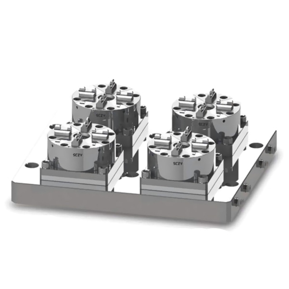
The 4-in-1 Base Plate Advantage
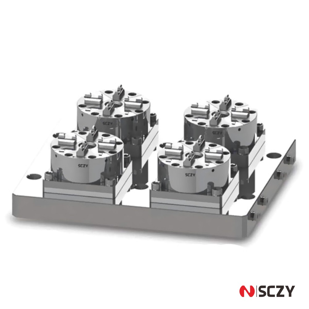
A 4-station pneumatic chuck layout mounts four independent chucks on one machined base plate. On our SC-G0006, the plate is 330 × 290 mm and each chuck is controlled by its own switch — so the operator loads fresh blanks into two chucks while the machine cuts on the other two. On short-cycle parts, this overlapping pattern routinely doubles spindle utilization without buying a second machine. Because all four chucks sit on one common reference plate, you also set work offsets once instead of four times.
When a Single Chuck with a Base Plate Still Makes Sense
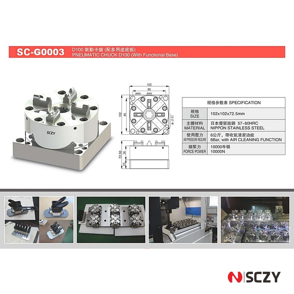
A single chuck on a functional base plate — like the SC-G0003 at 102 × 102 mm footprint — is the right choice when part size varies widely between jobs, when you need to relocate the fixture between machines, or when you’re piloting pneumatic workholding before committing to a full multi-station plate. The base plate gives you dowel and bolt patterns for mounting to vise jaws, tombstones, or dedicated subplates, and the whole assembly can be swapped in minutes.
Specifications That Actually Matter When Comparing Quotes
Two pneumatic chucks with the same jaw diameter can differ enormously in build quality. Before you compare prices, check these items:
Body and Jaw Material
Ask for the steel grade and hardness. A chuck body in hardened stainless or alloy steel (57–60 HRC) resists wear from abrasive chips and coolant. Soft-bodied chucks are cheaper and will develop jaw guide wear that shows up as runout and lost repeatability — usually just after the warranty ends.
Jaw Stroke and Jaw Options
Radial jaw stroke determines the part size range one chuck can handle. More stroke means fewer changeovers between part families. Also check whether soft jaws, serrated hard jaws, and stepping jaws are available — the jaw selection often matters more than the chuck itself.
Air Cleaning Function
Some pneumatic chucks include a burst of air at the clamping interface each cycle, blowing chips off the jaws before the workpiece seats. On aluminum and cast iron work, this single feature prevents most “part seated on a chip” scrap events and is worth requesting explicitly.
Sealing and Coolant Resistance
If the chuck lives under flood coolant or through-spindle coolant spray, confirm the seal package is rated for it. Emulsion that wicks past a piston seal turns a pneumatic chuck into a bench ornament within weeks.
Sizing the Air Supply and Controls
A 10,000 N chuck at 6 bar is not demanding, but sloppy air ruins the experience. Three practical rules:
- Fit an FRL unit (filter–regulator–lubricator) at the machine. Water and grit in shop air are the main killers of pneumatic chucks. The regulator also lets you dial clamping force down for delicate parts.
- Check flow, not just pressure. A 4-station plate that clamps four chucks simultaneously needs enough flow that pressure doesn’t sag during actuation. Small-bore drop lines are the usual culprit.
- Think about fail-safe behavior. Decide deliberately whether you want jaws to open or stay clamped on air loss. For most CNC milling with spindle-down cuts, spring-clamped or normally-clamped logic protects the part and the cutter if the compressor trips mid-cycle.
Real-World Setups Where Pneumatic Chucks Pay Off
Shops that see the fastest payback share a few profiles: electronics housings and connector blocks machined in batches of a few hundred; 5-axis workholding where parts are pre-machined on a pneumatic plate then transferred; medical and watch components where grip marks must be light and repeatable; and second-operation milling stations where load time dominates. In each case the economics are the same — the chuck costs a few hundred dollars, and saving 30 seconds per load on a 2-minute cycle pays it back within weeks of running two shifts.
Setup and Maintenance Checklist
To keep clamping force and repeatability stable over years:
- Mount the chuck or base plate on machined datum surfaces; indicate the chuck face within 0.01 mm TIR before tightening the bolts.
- Set the regulator to the rated pressure and lock it — operators turning pressure down “to be safe” is the most common cause of parts slipping.
- Drain the FRL filter daily in humid climates; refill the lubricator with the oil grade the manufacturer specifies.
- Clean jaw serrations weekly and inspect for embedded chips; a chip in a jaw tooth costs more scrap than a week of maintenance.
- Check clamped-part push-off force monthly with a force gauge, and log it — a falling trend catches seal wear before it catches you.
The Bottom Line
Choosing a pneumatic chuck for CNC machining comes down to three calls: enough clamping force for your cuts (10,000 N at 6 bar covers the vast majority of small-part milling), the right layout for your cycle time (multi-station plates for short cycles, single chuck on a base plate for mixed work), and clean, regulated air to protect the investment. Get those right and the chuck quietly earns its place on the table for a decade.
SCZY supplies pneumatic chucks in single and 4-station configurations, with matching base plates, jaws, and valve kits — alongside a full range of tool holders, collets, and CNC workholding. Send us your part drawing and batch size, and our engineers will recommend a clamping layout with a quote for a small trial order.