Most shops reach for a vise, a collet chuck or a magnetic chuck long before they consider a vacuum chuck for CNC machining. That is usually the right instinct — vacuum is the weakest of the three in raw holding force, and it will not survive a heavy roughing pass. But vacuum is also the only one of the three that can clamp a 3 mm aluminium plate, a graphite electrode or a piece of 304 stainless without touching its edges. This guide covers what vacuum clamping can and cannot do, how it compares with magnetic and pneumatic workholding on the same machine table, and how to specify a plate and pump that actually hold the part instead of leaking.
How a vacuum chuck holds a part
A vacuum chuck does not pull the part down. It removes air from beneath the part so that atmospheric pressure pushes it down. The clamping force is therefore the pressure differential multiplied by the sealed area — nothing more.
At a realistic working vacuum of −70 to −85 kPa, the differential is roughly 7 to 8.5 N/cm². A 300 × 300 mm plate has 900 cm² of area, which gives about 6,300 to 7,600 N if every square centimetre were sealed. In practice a machined plate seals perhaps 55–75% of its nominal footprint because of edge overhang, holes, slots and sealing land width, so plan on 3,500–5,500 N for that plate.
That number sounds healthy until you look at shear. Vacuum clamping produces almost no lateral resistance of its own. The part is held against sliding only by friction at the interface, and dry aluminium on steel gives a coefficient of friction of roughly 0.15–0.25. A 4,000 N normal load therefore resists only 600–1,000 N of side load. This is the single most important fact in vacuum workholding: vacuum is excellent at resisting lift and poor at resisting push. Design around it with hard stops, dowels or a pocket wall, and vacuum becomes reliable. Ignore it and the part walks.
Vacuum vs magnetic vs pneumatic: an honest comparison
The three methods are often marketed as alternatives, but they solve different problems. The table below compares them on the criteria that decide a fixture in a real shop — material, force, behaviour on thin parts, cycle time and cost.
| Criterion | Vacuum chuck | Electro-permanent magnetic chuck | Pneumatic chuck |
|---|---|---|---|
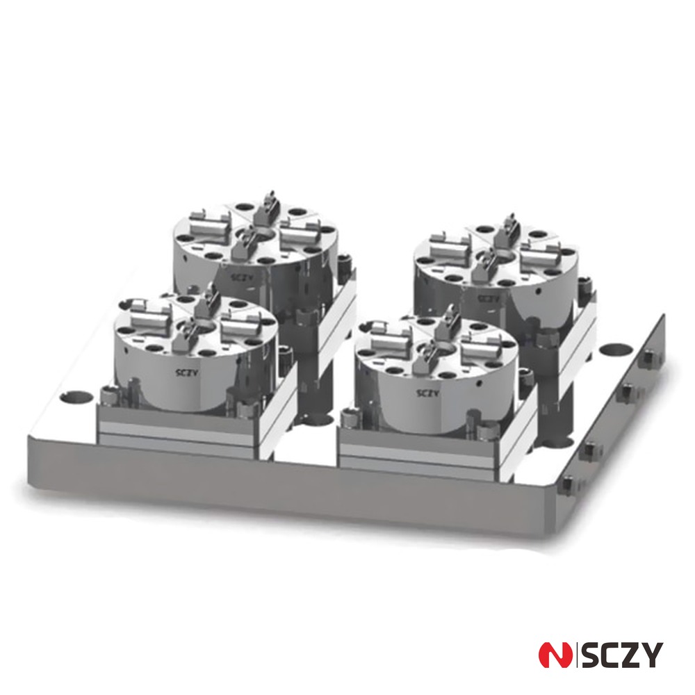
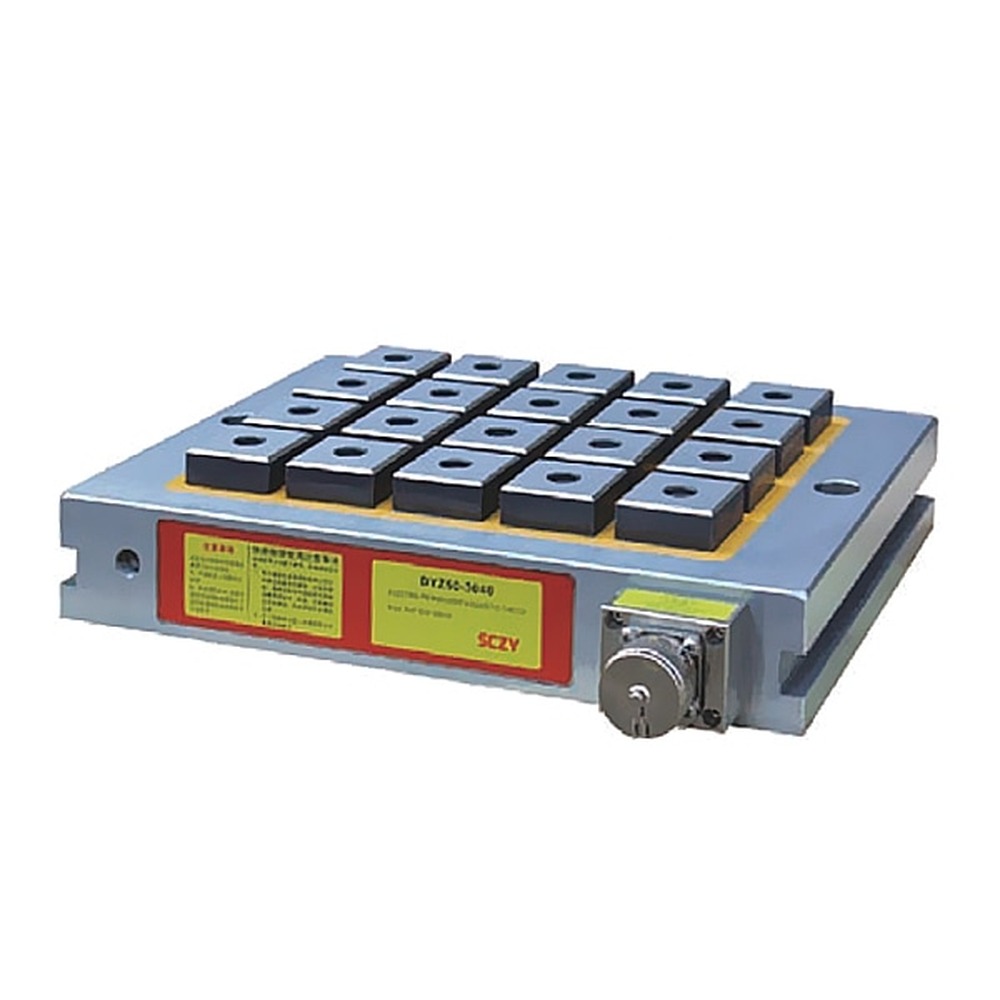
| Materials it can hold | Any non-porous material: aluminium, stainless, titanium, copper, brass, graphite, glass, ceramics, composites | Ferromagnetic only: steel, cast iron, some tool steels. No effect on aluminium or 304/316 | Any material, but the part needs a defined OD or ID for the jaws or collet to grip |
| Typical clamping pressure | 7–8.5 N/cm² at working vacuum, before sealing losses | 60–120 N/cm² with fine-pole design, about ten times vacuum | 2–6 kN per station, concentrated on the gripping diameter |
| Effect on thin parts | Very low distortion — pressure is uniform and normal to the face | Can pull thin steel into the pole pattern and print a shadow on the finished surface | Radial jaw force can collapse thin-wall parts; needs soft jaws or a collet |
| Lateral (shear) capacity | Friction only — usually the limiting factor | Friction only, but the much higher normal force helps | High — jaws resist side load mechanically |
| Cycle time | 1–3 s to pump down; 0.3 s to release with a reservoir | Under 1 s on/off, no plumbing | 0.5–1 s clamp/unclamp |
| Fixture cost | Plate plus pump, valve, filter and reservoir — the highest entry cost | Chuck only, no pump, but limited to steel | Chuck plus air preparation; per-station cost rises with station count |
| Best fit | Thin plate, non-magnetic material, full five-sided access, fine finishing | Flat steel and cast iron, grinding, heavy stock removal on magnetic material | Prismatic parts, multi-station production, high-volume small parts |
The comparison makes the decision fairly clear. If the part is steel and flat, a magnetic chuck gives ten times the normal force with no plumbing. If the part has a gripping diameter and you need volume, a pneumatic chuck wins on cycle time and side load. Vacuum earns its place where neither of those conditions is true.
Where vacuum clamping is the right answer
Non-magnetic materials
This is the largest category. Aluminium, 304 and 316 stainless, titanium, Inconel, copper, brass, graphite, glass, ceramics and CFRP are all invisible to a magnetic chuck. For these, the realistic options are mechanical clamping, adhesive fixturing or vacuum. On a flat part with a machinable face, vacuum is the fastest and least distorting of the three.
Thin plate and sheet
Below about 6 mm in aluminium, jaw clamping starts to work against you: the part deflects between the jaws, the cut releases residual stress, and the finished thickness varies across the plate. Vacuum supports the whole face, so the part stays where the plate holds it. Vacuum plates are routinely used down to 0.5 mm copper and 1 mm aluminium, provided the plate is flat and the seal is intact.
Five-sided access and clean faces
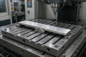
With vacuum there are no clamps, jaws or straps above the part. The tool can reach the entire top face and all four edges in one setup, and there are no jaw marks to blend out afterwards on cosmetic parts. On a part that needs its outline profiled and its face pocketed in the same operation, that access is often worth more than the holding force lost.
Delicate surface finishes
Polished, anodised or ground faces cannot tolerate jaw contact. Vacuum loads the part evenly on a face that is usually non-functional, which is why it is standard in glass and graphite electrode work.
Where vacuum will let you down
Being honest about the failure modes saves more money than any specification sheet.
Heavy roughing and interrupted cuts
As the friction calculation above shows, vacuum cannot be trusted to hold a part against a 1,500 N side load. If the operation removes more than a couple of millimetres of material per pass, or if the cutter is entering and exiting the part, use vacuum for finishing only, or combine it with mechanical stops that take the load.
Porous, warped or laser-cut parts
Castings, sintered parts, raw plate with mill scale and laser-cut edges all leak. So does any part that is not flat enough to seat on the sealing land — a 0.2 mm bow across a 200 mm plate is enough to lose vacuum on one side. If the part will not sit flat under hand pressure, vacuum is the wrong process until it has been faced.
Small footprints and broken seals
Force scales with sealed area, so a 40 × 40 mm part gives roughly 1,000 N at best and much less once edge effects are counted. Any hole, slot or counterbore crossing the seal ring also opens the circuit. Small parts need a dedicated sealing insert or a zoned plate, not a shared 300 × 300 mm surface.
Specifying the pump and plate
Size the pump on leakage, not on volume
The most common specification error is sizing a pump by the volume under the part. The volume matters only for pump-down time; what matters for steady-state holding is leakage — the air that leaks past the seal, through the part or through the plumbing.
A practical method: assemble the fixture, pull vacuum with the part in place, close the valve and time the decay. If the gauge rises from −80 kPa to −60 kPa in 60 seconds with a 2 L volume under the part, the leak rate is a few litres per minute at that vacuum level. Choose a pump rated at two to three times that figure at the working vacuum, not at open flow. A pump chosen this way will hold vacuum through a long finishing cycle even as the seal wears.
Use a reservoir and a valve
A small tank between the pump and the plate decouples the two. It lets you clamp, close the valve and cut while the pump catches up, and it holds the part briefly if power or air is interrupted. On a multi-zone plate, one pump can then serve several zones without pressure dropping each time a zone opens.
Plate layout
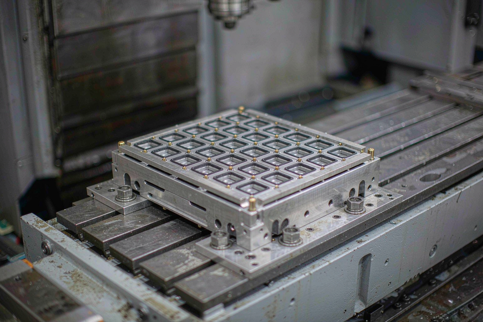
Three dimensions decide whether the plate works: seal groove position, groove cross-section, and support. A seal land of 3–5 mm under the part edge is typical; a groove 4 mm wide by 4–5 mm deep takes a 5 mm cord O-ring with 15–25% squeeze. Support pins or a machined grid should carry 60–70% of the part area so the part does not deflect into the vacuum pockets under cut pressure. And any plate expected to hold different part sizes should be split into zones with individual valves, because one large chamber cannot hold a small part.
Keeping vacuum reliable in production
Leak-down test as a routine
Once a shift, clamp a known flat plate, close the valve and watch the gauge for 30 seconds. A decay of more than 10 kPa means a worn seal, a scored plate face or a leaking fitting — and it will get worse. Recording the number turns a mysterious scrapped part into a maintenance ticket.
Seals, coolant and chips
Coolant attacks most seal materials and swarf embeds in the groove. Wipe the plate and the seal land before every load, keep a chip guard over the vacuum port, and treat the O-ring as a consumable with a defined replacement interval rather than something to be replaced after a failure. A filter on the vacuum line is cheap insurance against chips reaching the pump.
Buying checklist
- Confirm the part material is non-porous and the face that contacts the plate is flat within about 0.1 mm.
- Calculate sealed area, not part area, then apply a 60% efficiency factor for realistic force.
- Check the shear load of the operation against friction from that force — add stops if it is close.
- Decide zoning before ordering: one part size per zone beats one large chamber.
- Specify the pump from measured leak rate at working vacuum, plus a 2–3× margin.
- Include a reservoir, a gauge, an isolation valve and a line filter in the bill of materials.
- Confirm seal material against the coolant used, and set a replacement interval at purchase.
Choosing the right clamping method
Vacuum, magnetic and pneumatic clamping are complementary tools, and most production cells end up using all three: magnetic for flat steel, pneumatic for prismatic parts in volume, and a vacuum chuck for CNC machining of thin, non-magnetic or cosmetic parts where nothing else can touch the part without marking or distorting it. Getting the choice right is mostly a matter of matching the material and the load case rather than chasing the highest holding force on a datasheet.
If you are specifying workholding for a new cell — or replacing a fixture that keeps losing its grip — SCZY can help you match the clamping method, chuck specification and tooling to the parts you actually run. Send us the part drawing, material and cut data, and we will come back with a recommendation and a quote.