Most aluminum jobs go wrong for the same boring reason: the wrong carbide end mill for aluminum was pulled out of the drawer. Aluminum is soft, so it feels forgiving. It is not. It is gummy, it conducts heat away from the cut almost instantly, and it has a stubborn habit of welding itself to a cutting edge the moment the geometry is wrong. A tool designed for steel will cut aluminum — badly, and not for long.
This guide covers the four decisions that actually determine whether an aluminum end mill performs: flute count, helix angle, coating, and the holder you put it in. No theory for its own sake, just what changes on the shop floor.
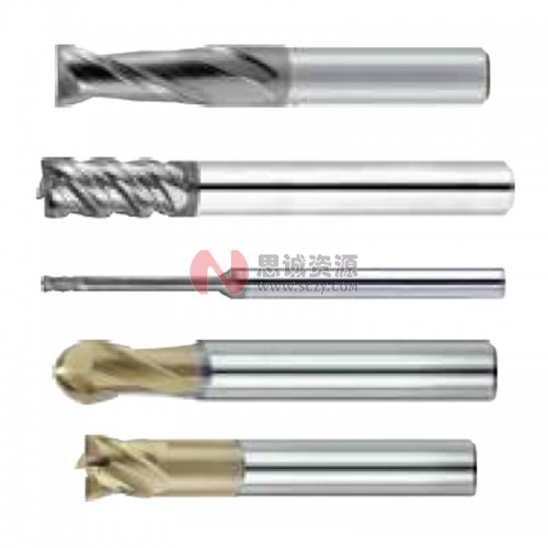
Why Aluminum Punishes the Wrong End Mill
Three material properties drive every tooling choice here.
Low melting point and high ductility. Aluminum shears cleanly only when the chip is evacuated fast and the edge stays sharp. Let a chip dwell for a fraction of a second and it pressure-welds to the flute. That is built-up edge (BUE), and once it forms, the effective rake angle changes, cutting forces climb, and surface finish collapses.
High thermal conductivity. Heat leaves with the chip rather than soaking into the workpiece, which is why aluminum tolerates very high surface speeds. It also means flood coolant matters less for cooling the part and more for flushing chips.
Thermal expansion. Aluminum moves roughly twice as much as steel per degree, so a tool that cuts cool and clean makes tight tolerances far easier to hold.
Flute Count: The First Decision
Flute count is chip room versus feed rate. Fewer flutes means more space per flute for the chip to leave, at the cost of feed per revolution. More flutes means more cuts per revolution — but where does the chip go?
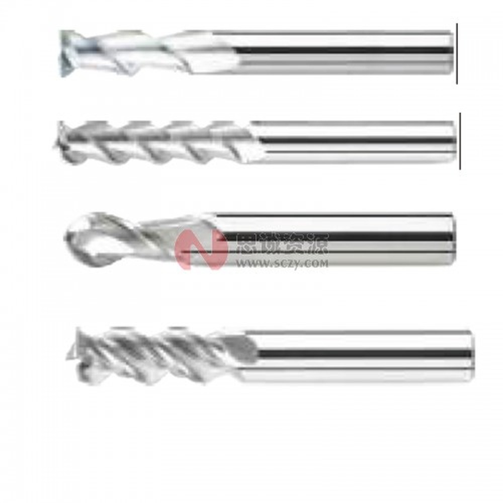
1-Flute: Routers, Plastics and Deep Pockets
Single-flute tools are standard on CNC routers and for deep cavity work where chip evacuation is the limit. They remove material slowly but almost never clog — useful for small-diameter deep slots and thin-wall work where a two-flute tool would pack the flutes.
2-Flute: The Aluminum Default
Two flutes is the right starting point for most aluminum milling, and it is what most job shops should keep stocked. Large flute volume handles the high chip load aluminum wants, plunge capability is good, and the core is thick enough for stability in small diameters. For slotting, ramping and general profile work in 6061, a 2-flute uncoated or ZrN tool at 35–40° helix is hard to beat.
3-Flute: The High-Speed Compromise
Three-flute tools trade a little chip room for 50% more teeth in the cut. In practice this means higher feed rates at the same chip load, which is exactly what high-speed machining strategies want: light radial engagement, large axial depth, constant chip thickness. The catch is chip evacuation. Three flutes work well with through-spindle coolant, air blast or MQL, and poorly in deep blind pockets with no coolant aimed at the cut. If your process is trochoidal or dynamic milling, three flutes is usually the better economics.
4-Flute and Above: Finishing Only
Four or more flutes leave too little room for aluminum chips at normal radial engagement. They are legitimate for finishing passes with very light radial depth (under 10% of diameter) at high feed, and for hard-to-machine high-silicon alloys, but they are the wrong tool for roughing aluminum. If a four-flute tool is chattering and packing chips in aluminum, it is not a feeds-and-speeds problem.
| Flute count | Chip room | Best use in aluminum | Watch out for |
|---|---|---|---|
| 1 flute | Maximum | Routers, deep slots, small diameters, plastics | Low feed rate, weaker core |
| 2 flute | High | General milling, slotting, ramping, roughing | Lower productivity than 3-flute in HSM |
| 3 flute | Medium | High-speed machining, trochoidal paths, finishing | Chip packing without coolant or air blast |
| 4+ flute | Low | Light-radial finishing, high-silicon alloys | Built-up edge and clogging in soft aluminum |
Helix Angle and Rake: Where Chip Evacuation Is Won
For aluminum, the standard helix is 35–40°. That range gives an efficient shearing action and lifts chips out of the cut without excessive axial force.
45° helix tools shear faster and produce excellent finishes at high feed, which is why they are popular for high-speed finishing of aluminum. The trade-off is axial lifting force: on thin floors, vacuum-fixture work or parts held by a small clamp, a high helix can pull the workpiece up. If you see the part lifting or floor thickness drifting, drop the helix before you blame the fixture.
Low helix (15–20°) reduces that lifting force and is the safer choice for slotting thin plates and finishing floors held on vacuum tables.
Variable helix and variable index geometries are worth the premium on long-reach and thin-wall work: they break up the harmonic that causes chatter, which in aluminum shows up as a ringing finish and fast edge wear. Rake matters too — aluminum tools need a high positive rake and a sharp, polished edge. A tool with a heavy edge hone designed for steel rubs before it cuts, and rubbing is what generates BUE.
Coatings for Aluminum: What Works and What Welds
Coating choice for aluminum is counterintuitive: the hardest coating is often the worst choice.
| Coating | Behavior in aluminum | Verdict |
|---|---|---|
| Uncoated, polished | Sharpest edge, no adhesion layer to wear through | Best default for 6061 and general work |
| ZrN | Low affinity for aluminum, good lubricity, keeps the edge sharp | Excellent all-round upgrade |
| DLC (diamond-like carbon) | Very low friction, strong anti-welding behavior | Best for sticky alloys and high-silicon content; mind service temperature |
| TiAlN / AlTiN | Hard and heat-resistant, but aluminum affinity and a duller edge | Wrong tool for aluminum — it welds |
| Diamond (PCD or CVD) | Extreme wear resistance, no aluminum adhesion | Justified for high-silicon die-cast alloys and volume production |
Two practical notes. First, a polished flute matters more than the coating label: surface roughness on the flute is where chips start to stick. Second, coatings add thickness to the edge. A coated tool that was not re-sharpened after coating will cut aluminum noticeably worse than an uncoated tool with a properly prepared edge.
For high-silicon aluminum — A356, 390 die-cast, anything above roughly 10% silicon — abrasive wear dominates and diamond becomes the economic answer. For 6061, 7075, 2024 and 5083, uncoated polished or ZrN is the sensible choice.
Shank, Holder and Runout: The Part Buyers Forget
You can specify the perfect tool and destroy it with the holder. Every 0.01 mm of runout at the cutting edge turns into uneven chip load: one flute cuts deep, the others rub. In aluminum that shows up fast as BUE on one flute and a poor finish.
Aim for total indicated runout of 0.01 mm or better at the tool tip. In practice:
- ER collet chucks are versatile and cheap, but a worn nut or a chip under the collet easily doubles runout. Check with a dial indicator, not by feel.
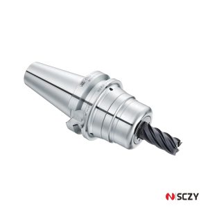
- Hydraulic holders clamp uniformly around the shank and hold runout well below 0.01 mm, which is why they pair well with small-diameter aluminum finishers.
- Shrink-fit holders give the best concentricity and stiffness, at the cost of a heater and a fixed shank tolerance.
- Side-lock holders are fine for roughing with a Weldon flat, but the set screw pushes the tool off center. Do not finish with them.
Balance matters above roughly 15,000 rpm. A G2.5 holder and a balanced assembly at your top spindle speed is a reasonable working standard; unbalanced tooling at 20,000 rpm produces vibration that looks exactly like a poor tool grind.
Starting Speeds and Feeds for 6061
Use these as a starting point for a sharp 2-flute carbide tool in 6061-T6 with good chip evacuation, then adjust on the first part. They assume a rigid setup and a holder with runout under 0.01 mm.
- Cutting speed: 300–500 m/min surface speed. A 10 mm tool lands around 10,000–16,000 rpm; start low and climb.
- Chip load: 0.02–0.04 mm per tooth for a 6 mm tool, 0.05–0.08 mm for a 10 mm tool, 0.08–0.12 mm for a 16 mm tool. Too light a chip load rubs instead of cutting and is a leading cause of BUE.
- Axial depth: up to 1× diameter in soft aluminum is normal for roughing; deeper with a 3-flute tool and high-pressure coolant.
- Radial depth: 50% of diameter or more for conventional roughing; 5–10% for high-speed dynamic paths, where you compensate with feed.
One rule outranks all of these: never let the tool dwell. A pause in the cut, a hesitation at a corner, or a feed override that drops to zero mid-pass will mark the part and start a BUE. Keep the tool moving or pull it out.
Troubleshooting: Five Symptoms and What They Mean
1. Chips welding to the flutes
Too much heat at the edge, too little chip load, or the wrong coating. Increase feed per tooth, check coolant direction, and switch to ZrN or DLC if the alloy is sticky.
2. Ringing finish and chatter marks
Usually tool overhang, holder runout, or a flute count that leaves no room for chips. Shorten the gauge length, check runout, then change geometry.
3. Premature corner wear
Corners take the load when the tool plunges or ramps hard. A small corner radius spreads it and often doubles edge life in roughing.
4. Oversize slots or drifting dimensions
Thermal growth or deflection, not tool wear. Check coolant coverage, reduce axial depth, and make sure a side-lock holder is not pushing the tool off center.
5. Good finish on the first part, poor by the fiftieth
Wear is gradual until BUE appears, then finish falls off a cliff. Log parts per edge and change on count, not on appearance.
What to Ask a Supplier Before You Order
Catalog pages list diameter, flute count and coating. That is not enough to compare two quotes. Ask for edge preparation (sharp, honed or polished, and whether coating comes after sharpening), substrate grade and cobalt content, a measured TIR figure rather than “high precision”, and how consistent the grind is batch to batch — a cheap tool that varies lot to lot costs more in scrap than it saves.
SCZY supplies solid carbide end mills for aluminum alongside the holders that go with them, so flute count, helix and holder runout can be matched as one package rather than three separate purchases. For a mixed shop that usually means a small standard set: 2-flute uncoated for general work, 3-flute ZrN for high-speed paths, and a corner-radius rougher for pocketing.
Getting the Aluminum End Mill Decision Right
The right carbide end mill for aluminum is not the most expensive one, and it is rarely the one designed for steel. Match flute count to chip room, helix to part geometry, coating to alloy, and holder to runout — and most of the problems that get blamed on feeds and speeds disappear.
If you are specifying tooling for a specific aluminum part or alloy and want a recommendation with real numbers instead of a catalog page, send us the drawing and the machine details. We will come back with geometry, coating and starting parameters.