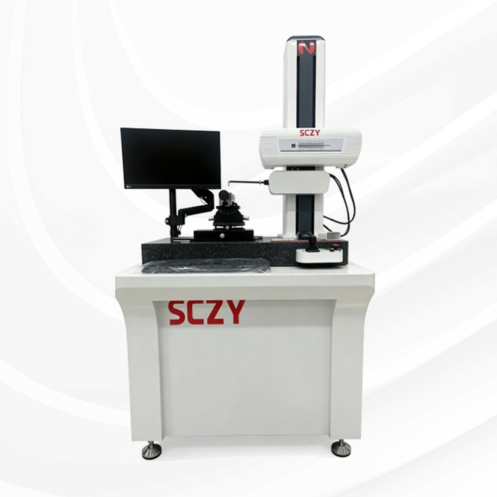
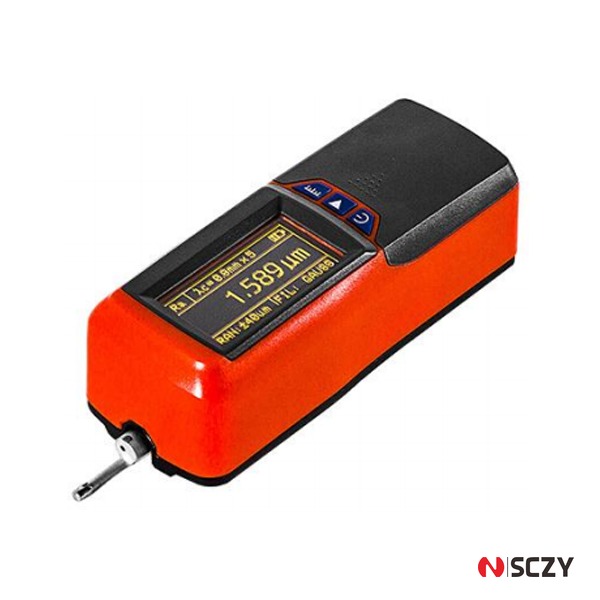
Most shops buy their first surface instrument backwards. They compare brands and prices before deciding which quantity they are trying to control, so a stylus profilometer gets judged against a handheld roughness tester on the only axis the catalogue makes obvious: price. They are not the same class of machine. One is a pocket gauge that answers “is this surface smooth enough right now”; the other is a bench instrument with a precision traverse datum, a motorized column and software that evaluates roughness and profile together. Choosing wrong rarely shows up as a rejection on day one. It shows up a year later, when a drawing starts calling out a radius or a groove depth and the gauge in the drawer has no way to report it.
What a Stylus Profilometer Actually Measures
A profilometer drags a diamond-tipped stylus across the surface at constant speed and records the vertical displacement of the tip against a reference. Filters, parameters and printed reports are all arithmetic on that single trace. Two consequences follow: the measurement is only as good as the datum, because the datum defines what “flat” means, and the trace is a line rather than an area, so two operators traversing different locations on the same part can both be correct and still disagree.
The measurement chain: pickup, datum, evaluation
Three components decide the result. The pickup turns vertical motion into a signal, normally through an inductive or piezo transducer with a measuring force in the 0.7–4 mN band — too much and soft materials such as aluminium or copper get scratched, too little and the stylus skips rather than follows. The datum comes either from a skid riding on the part or from the traverse guide. The evaluation software applies cutoffs and computes parameters, and that is usually where supplier and customer arguments are actually settled.
Resolution is not accuracy
Data sheets quote 0.001 µm and 0.01 µm resolution almost interchangeably, and neither describes the error you will live with. What matters is residual straightness error of the traverse over the evaluation length, Z-axis linearity across the range you use, and repeatability of repositioning a part. A machine with 0.01 µm resolution but half a micron of traverse bow cannot certify 0.2 µm Ra, and no software corrects it. Ask for straightness in microns per traverse length.
Roughness Tester, Stylus Profilometer, Contour Station
The three classes differ in travel, reference and software, and those differences map onto part size and drawing callouts. The table below is the decision matrix worth carrying into a quotation meeting.
| Capability | Handheld roughness tester | Bench stylus profilometer | Contour / form station |
|---|---|---|---|
| Traverse length | 0.25–17.5 mm typical | 50–200 mm | 150–500 mm, or rotary |
| Powered axes | Z only; operator positions X | X and Z motorized, column with auto height | X, Z, plus rotary table or Y |
| Reference datum | Skidded pickup | Skidless traverse on granite base | Air-bearing or precision ground slide |
| Typical parameters | Ra, Rz, Rq, Rt, Rmax | Full Ra–Rku set, Rk family, Motif, plus radius, angle, distance | Roughness, contour, roundness, cylindricity, position |
| Parts it suits | Rolls, shafts, large castings, in-process checks | Small to medium parts staged on a bench, grooves, threads, seal profiles | Precision parts with form and position callouts |
| Throughput | Seconds per reading, no setup | 1–5 min per part including fixturing | 5–30 min per part |
| Indicative budget | USD 700–2,500 | USD 8,000–35,000 | USD 30,000 and up |
| Footprint | About 1 m² of bench | Dedicated metrology room |
The overlap is narrow. A bench profilometer can measure a 200 mm shaft if the column is tall enough and the part can be supported; a handheld tester cannot measure a seal groove radius no matter who holds it. Where a drawing set mixes Ra callouts with radius or angle callouts on the same part family, the profilometer is the only one of the three that reports both from one setup.
Skidded or Skidless: The Pickup Decision Nobody Explains
A skidded pickup carries a curved shoe that rides on the surface a few millimetres ahead of the stylus and serves as the reference. It is robust, indifferent to part orientation, and it works on a lathe bed. It is also a mechanical filter: the skid averages the surface over its contact length, so long-wavelength waviness is partly absorbed into the datum and short-wavelength features can be attenuated. On fine-turned or ground surfaces whose pitch approaches the skid length, a skidded instrument reads noticeably lower Rz than a skidless one.
What the skid does to your data
Removing waviness is exactly what you want when the callout is roughness only. It becomes a problem when the same trace is used to judge form — a 20 µm bow across a 12.5 mm evaluation length will be partly hidden. Where a drawing mixes Ra with a straightness or profile tolerance, run the two checks from separate traverses.
When only a skidless traverse works
Skidless instruments use the traverse guide as datum, which makes them mandatory for small radii, sharp steps, narrow grooves and any feature the skid would bridge. The cost is fragility, price, and a hard requirement for a stiff granite base — a skidless pickup on a bench that flexes when someone leans on it reports noise that looks like roughness.
Stylus Geometry: What a 2 µm Tip Cannot See
ISO 3274 sets the default stylus as a 90° cone with 2 µm tip radius, in practice a truncated cone with a nominal 5 µm flat. That geometry is a mechanical low-pass filter. A V-groove narrower than roughly four times the tip radius is never fully penetrated, so the stylus bridges the valley and reports less depth and a lower Rz than the part has. On fine-turned surfaces with 0.2 mm pitch this can understate Rz by a third, and the error is systematic — more measurements do not average it out.
Use a 2 µm tip for finishing and small radii, a 5 µm tip for coarse castings or shot-blasted moulds where a sharp diamond would be damaged, and accept that deep narrow grooves belong to an optical method. Tip wear belongs in the weekly routine too: a chipped diamond reads high Ra on every part, and because the drift is gradual nobody notices until a customer rejects a batch the instrument had passed.
Cutoff, Evaluation Length and Why Two Labs Disagree
Ra alone is not a specification. Every Ra figure is the output of a filter setting, and ISO 4288 ties cutoff wavelength λc to the magnitude being measured. Applying λc 0.8 mm to a surface that needs 2.5 mm produces a smaller number that looks like an improvement and means nothing.
Selecting cutoff from the expected Ra
- Ra up to 0.1 µm: λc 0.25 mm, evaluation length 1.25 mm
- Ra 0.1–2 µm: λc 0.8 mm, evaluation length 4 mm
- Ra 2–10 µm: λc 2.5 mm, evaluation length 12.5 mm
- Ra 10–80 µm: λc 8 mm, evaluation length 40 mm
Evaluation length is conventionally five cutoff lengths, and the number of sampling lengths affects Rz more than Ra — one reason two competent labs can disagree by 20 percent and both be right.
Write the filter on the drawing
One line removes most of the ambiguity: “Ra 0.8, λc 0.8, Gaussian filter, evaluation length 4 mm, measured across the lay.” Add the standard revision. Rz changed definition between the 1997 and 2006 versions, and ISO 21920 is now replacing 4287 and 4288 in new drawings, so a supplier working from an old template and a customer quoting a new value can be describing different quantities with the same symbol.
Contour Measurement: The Jobs Ra Cannot Describe
With a calibrated X axis, the same stylus maps a profile: radius, angle, distance, step height and deviation from nominal form. For many shops this is what pays for the machine, because those callouts are currently checked with radius gauges and shadowgraphs that yield an opinion rather than a number.
Seal grooves and pulley profiles
An O-ring groove is defined by width, depth, bottom radius and flank angle, and a seal fails on any one of them. A bench profilometer evaluates all four in one traverse and prints deviation against nominal, which turns a leak discussion into a conversation about numbers. Belt pulley and thread forms behave the same way: the geometry is a chain of radii and angles, and a per-feature gauge measures one link at a time.
Threads, radii and transition zones
Thread work is limited by the same tip geometry — crest radii under about 0.05 mm are not resolvable with a 2 µm stylus — but pitch, flank angle and root radius on coarse threads are well within reach if the traverse captures several pitches. Fixturing matters more than the instrument: a thread not aligned with the traverse plane produces a flank angle error that looks like a manufacturing defect.
A Selection Checklist for the RFQ
Five questions that decide the class
- What is the largest part, and can it be brought to a bench? If not, a handheld instrument is the honest answer.
- Does any callout require radius, angle or distance? If yes, roughness-only instruments are excluded.
- What is the finest Ra you must certify? Below 0.1 µm, traverse straightness and thermal stability dominate the specification.
- How many parts per shift? Above about twenty, fixturing and report automation matter more than resolution.
- Who reads the output? If it is a customer’s quality department, report format and standard revision are part of the requirement.
What to specify in the purchase order
Put in writing: traverse length and straightness error over that length; Z range and linearity; tip radius and measuring force; the standards the software evaluates against, including revision; calibration artefacts supplied; granite base size and whether the column is motorized; and report output format. Two items are usually forgotten — the environmental envelope the accuracy figures are valid in, and whether the software accepts your own evaluation length and filter settings rather than presets only.
Common Mistakes in Surface Finish Inspection
- Measuring along the lay instead of across it. A turned surface read along the tool marks can show a third of the true Ra.
- Comparing skidded and skidless data. Different datum, so the numbers are not interchangeable.
- Reporting Ra only. Two surfaces with identical Ra can differ threefold in Rz and behave completely differently in a seal.
- Ignoring part temperature. A part straight off the machine is not at 20 °C; the instrument was calibrated there.
- No reference specimen check. A worn stylus produces plausible numbers on every part, which is why the drift goes unnoticed.
Matching the Instrument to the Work
A stylus profilometer earns its bench space when the drawing set mixes roughness with geometry and the parts are small enough to stage. Where the requirement is a bare Ra value on a shaft that stays in the machine, a handheld roughness tester remains the efficient answer. The expensive mistake is buying the handheld first, discovering the radius callouts a year later, then buying the bench instrument anyway while the handheld gathers dust.
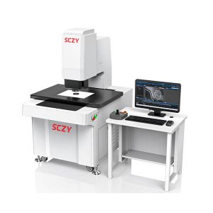
SCZY supplies both ends of that range — benchtop stylus profilometers with granite bases and evaluation software, and portable roughness testers for in-process checks — alongside the tool holders, workholding and cutting tools that produce the surfaces being measured. If you are specifying an inspection instrument and want a second opinion on which class fits your drawing set, send us the parts, the callouts and the volume. Get in touch with the SCZY team and we will put the comparison in writing.
GET A QUOTE
Looking for metrology equipment for surface and contour inspection?
Explore our product range or send us your requirements. Our team will be glad to review your inquiry.