If your shop machines molds, dies, impellers or any part with blended 3D surfaces, the ball nose end mill is probably the tool that touches the most critical geometry you make. It is also the tool most often run with the wrong stepover, the wrong rpm or the wrong expectations — which is why so many “bad surface finish” problems trace back to how the ball profile was applied, not to the tool itself.
This guide covers the two numbers that decide your finish — stepover and scallop height — the speed correction most CAM users skip, and an honest ball nose versus bull nose versus flat comparison, so you know when a cheaper corner-radius tool does the job better.
How a Ball Nose End Mill Actually Cuts
A ball nose end mill is a milling cutter with a hemispherical cutting end. Every point on the ball sits at a different distance from the spindle axis, which means every point along the profile cuts at a different surface speed. At the very tip center, the effective cutting diameter is zero — that point does not cut so much as rub and smear its way through the material. Moving up the ball, effective diameter grows until it equals the tool diameter at the equator of the sphere.
Effective Diameter Drives Your RPM
When your radial stepover is a small fraction of the tool diameter — which it almost always is in finishing — the tool only uses a sliver near the tip, where the effective diameter is far smaller than nominal. A 6 mm ball nose with a 0.3 mm stepover has an effective cutting diameter of roughly 2.6 mm, not 6 mm. Calculate rpm from the nominal diameter and you run at less than half the intended surface speed. Let your CAM system handle it, or use Deff = 2 × √(ae × (D − ae)), where ae is the stepover. On a capable spindle this routinely means finishing at 15,000–30,000 rpm instead of 8,000.
Chip Thinning at Small Stepovers
The same small radial engagement that reduces effective diameter also thins the chip. At a 0.3 mm stepover on a 6 mm ball, actual chip thickness is well below the programmed feed per tooth. Run the chart feed without compensating and you rub instead of shear — heat goes into the tool instead of the chip, and edge life collapses. Apply a chip thinning factor and raise the feed; most CAM systems do this automatically once you set the true radial engagement.
Stepover and Scallop Height: The Numbers That Set Your Finish
The Scallop Height Formula
Between successive passes, a ball nose leaves a cusp — the “scallop” you can see and feel on the finished surface. For a ball nose, scallop height is h ≈ so² / (8 × R), where so is the stepover and R is the ball radius. The quadratic relationship is the whole story: halving the stepover cuts scallop height to a quarter.
Worked example: a 6 mm ball (R = 3 mm) at a 0.3 mm stepover leaves cusps of about 0.0038 mm — roughly 3.8 microns, comfortably inside a no-hand-polish Ra target for most die surfaces. Tighten the stepover to 0.15 mm and the scallop drops below 1 micron, but cycle time doubles. Finishing strategy is a negotiation between floor time and polish time, not a search for one magic number.
Practical Stepover Ranges
| Application | Typical Stepover (% of ball Ø) | What You Get |
|---|---|---|
| Semi-finishing after roughing | 10–20% | Even stock left for finishing; fast coverage |
| Standard 3D finishing, steel molds | 5–10% | Scallops of 2–5 µm on D6–D12; no polishing on non-cosmetic faces |
| Cosmetic or optical surfaces | 2–5% | Sub-micron scallops; plan for long cycle times or a smaller ball |
| Graphite and copper electrodes | 5–10% | Fast passes; edge quality governed more by substrate than stepover |
One more practical note: on steep walls, constant-stepover passes leave growing scallops because the effective step across the surface stretches. Use a constant-scallop strategy with variable stepover, or tilt the tool in steep regions as described below.
Ball Nose vs Bull Nose vs Flat End Mill
Ball nose end mills get picked by habit for jobs a corner-radius (bull nose) tool would finish faster and better. Before defaulting to the ball, compare the three profiles honestly.
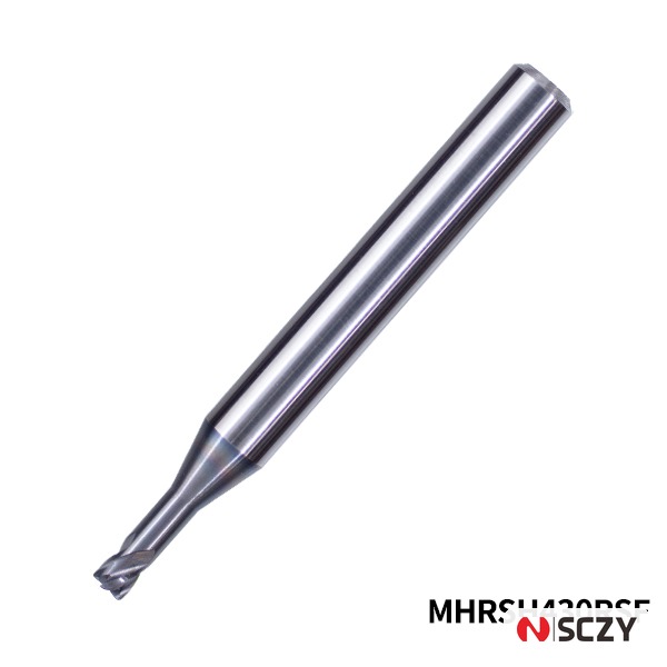
| Attribute | Ball Nose | Bull Nose (Corner Radius) | Flat (Square) End Mill |
|---|---|---|---|
| Best suited for | 3D contoured surfaces, blend radii, undercuts | 2.5D pockets, floors with wall fillets, steep walls | Sharp internal corners, slotting, shoulder milling |
| Surface on flat floors | Poor — point contact leaves cusps even at tiny stepover | Excellent — full-width bottom cutting edge | Excellent |
| Surface on 3D contours | Excellent — uniform cusp geometry, predictable Ra | Limited — works on gentle slopes only | Not applicable |
| Cutting speed at tip | Zero at center — needs tilt or offset on steep work | Full speed across the bottom edge | Full speed across the bottom edge |
| Corner geometry left behind | Sweeps a radius, no sharp corner possible | Leaves a defined corner radius | Leaves a sharp corner |
| Typical failure mode | Tip chipping, rubbing on steep walls | Corner-edge chipping under heavy radial loads | Corner breakage, chatter in deep pockets |
Where the Ball Profile Wins
Any continuously curved surface — core and cavity geometry, turbine blades, port work — is ball nose territory. The ball sweeps a constant-radius path, so cusps are uniform and predictable, blend lines between passes are invisible, and one tool finishes surfaces that would otherwise need a dozen flat tools of different corner radii.
Where a Bull Nose or Square End Wins
When the part is mostly flat floors with filleted walls, a corner-radius tool finishes the floor with full-width engagement at proper surface speed, takes heavier radial cuts on the wall, and lasts longer doing it. The zero-speed tip of a ball nose crawling across a flat floor is the slowest, most heat-generating way to make a flat surface. Rule of thumb: if more than about 70% of the finishing geometry is planar, lead with a bull nose and bring the ball in for the curved regions only.
Flute Count, Neck Geometry and Reach
Most ball nose finishing work in mold steel runs two or four flutes. Two flutes give generous chip room, which matters in aluminum, graphite and deep-slot work where chips travel a long way out. Four flutes roughly double the feed per revolution at the same chip load per tooth, which is why they dominate high-speed finishing in hardened steel where chip volume is small.
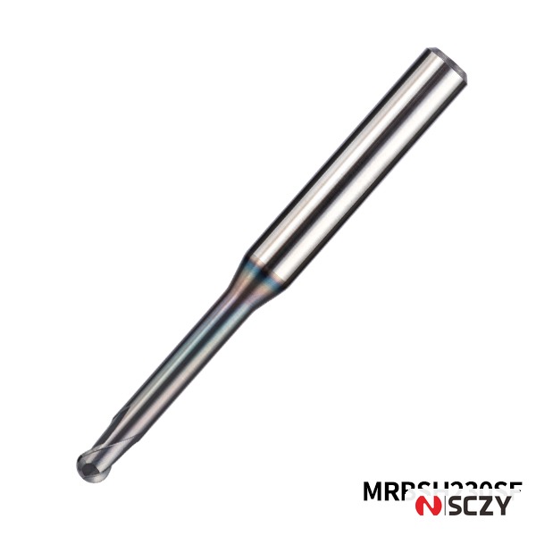
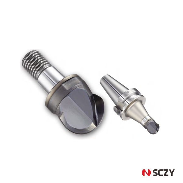
Reach is where ball nose tools fail physically. Deep ribs, narrow pockets and parting-line grooves force either long-series tools or necked designs. A necked ball nose — a carbide shank relieved to a reduced neck diameter behind the flutes — reaches where a long-series tool cannot, with far better rigidity because the relieved section is short. Match neck length to actual depth plus 1–2 mm of clearance, not more: every millimeter of unsupported reach adds deflection and chatter risk. Replaceable-head systems extend this logic — the body stays in the holder while a threaded carbide head is swapped, cutting tooling cost on high-volume electrode and cavity work.
Substrate, Coating and Material Matches
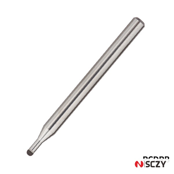
Fine-grain carbide with a TiAlN or AlCrN coating covers most ball nose applications in steels up to about 50 HRC. Beyond that, the substrate match matters more than brand names: for hardened die steel from the mid-50s HRC upward, CBN ball noses hold their edge where coated carbide starts to deform. For graphite electrodes, copper, carbon composites and high-silicon aluminum, PCD ball noses outlast carbide by an order of magnitude — graphite in particular is brutally abrasive.
Coatings interact with the workpiece too: DLC-type films reduce graphite and aluminum sticking in deep flutes, while for titanium you want heat carried into the chip, favoring sharp thin-film edges and high-pressure coolant where the machine has it.
Common Ball Nose Failures and Fixes
Tip Chipping
The tip is the weakest, slowest-cutting point on the tool. Chipping there usually means the tool is feeding on its zero-speed center — typically when climbing steep walls head-on. Tilt the tool or the head 10–15° off vertical in 3+2 mode so the effective cutting zone contacts the wall, and ease the feed where engagement spikes.
Rubbing and Work-Hardened Skin
If the surface looks burnished rather than machined, and hardness readings on the wall come back high, you are chip-thinning without feed compensation, or running too slow for the effective diameter. Recalculate rpm with Deff and raise feed to a real chip thickness.
Chatter on Deep Finishes
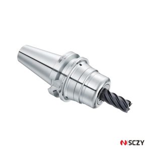
Long reach amplifies everything. Reduce overhang to the minimum, and move from a collet chuck to a shrink-fit or hydraulic holder when runout and rigidity matter. If you are seeing wear inside the holder taper after high-speed runs, check the contact before blaming the tool — our tool holder taper wear guide shows how.
Tool Holding: Give the Tool a Fair Chance
A ball nose finishing pass magnifies holder problems, because small stepovers turn any runout into visible step differences between passes. Shrink-fit and hydraulic chucks give the best combination of runout and balance at finishing speeds; ER collets are perfectly serviceable for most work as long as you know what your assembly actually measures — our ER collet runout guide covers realistic TIR figures by accuracy grade. For heavy interpolation and ramping on roughing passes, side-lock (Weldon) holders still earn their place by preventing pull-out — see the side lock end mill holder guide for screw torque and Weldon flat details.
If the work is primarily aluminum, pair the ball nose with the holder and parameter choices from our carbide end mills for aluminum guide — the same two-flute logic applies to ball profiles.
Ball Nose Selection Checklist
- Diameter from geometry: the ball must fit the smallest fillet it has to produce, and stay large enough that the effective diameter at your finishing stepover still supports a sane rpm.
- Neck length = depth + clearance: no more. Order the shortest neck that reaches.
- Flutes: two for chip room and soft or abrasive materials, four for high-speed finishing in steels.
- Substrate by hardness: carbide with AlCrN to about 50 HRC, CBN above that, PCD for graphite, copper and composites.
- Holder: shrink-fit or hydraulic for finishing; verify runout at the nose, not the shank.
- CAM settings: effective-diameter speed compensation, chip-thinning feed compensation, tool tilt on steep walls.
Source Ball Nose End Mills From SCZY
SCZY supplies long-neck ball nose, bull nose and replaceable-head ball end mills in carbide, CBN and PCD substrates, along with the shrink-fit, hydraulic and side-lock holders that let them cut to spec. Whether you need catalog sizes for die maintenance or custom neck geometries for a production cavity, we can quote from a drawing and advise on parameters for your material.
Want a quote or a recommendation for a specific mold or electrode job? Contact SCZY and tell us the material, hardness and depth you are working with — our engineers will come back with a tool proposal and cutting parameters.